Modular room system and method

a modular and room technology, applied in the field of room structures, can solve the problems of only being able to both alternatives can be expensive, and the structure can only be altered by incurring the cost of additional construction or demolition, so as to achieve stronger and more stable upright, increase stability and strength, and increase the effect of stability and strength

Inactive Publication Date: 2007-08-23
L & P PROPERTY MANAGEMENT CO
View PDF34 Cites 16 Cited by
  • Summary
  • Abstract
  • Description
  • Claims
  • Application Information

AI Technical Summary

Benefits of technology

[0016] In order to address many of the problems and limitations of the prior art described above, some embodiments of the present invention employ a modular room including a plurality of modular room components (e.g., anchor assemblies, upright assemblies, etc.). These anchor assemblies and upright assemblies can take different forms permitting assembly of a modular room or modular structure in a number of different manners. This flexibility enables a user to assemble a modular room or structure in different sizes, shapes and layouts using a relatively small number of elements and components. By assuming a variety of different sizes, shapes and layouts, the modular room or modular room structure can be flexible to accommodate different layouts of larger structures in which the modular room can be located.
[0017] As discussed above, it is also desirable to have a modular room or a modular room structure that is quick and easy to assemble and disassemble and preferably employs modular elements and components. Some embodiments of the present invention employ a reduced number of different component and element types (e.g., sizes), thereby simplifying manufacturing and assembly and reducing the cost of such operations. For example, some or all of the components and elements of a modular room that are employed to construct an exterior wall of the modular room are preferably the same as those employed to construct an interior wall of the modular room.
[0018] For purposes of increased stability and strength, some embodiments of the present invention have an upright assembly that includes a substantially vertical elongated upright and a bracket coupled to a bottom end of the upright. The upright can have a wall partially defining an interior of the upright and at least one aperture in the wall. The bracket can have a first portion received within the aperture of the upright that extends into the interior of the upright and releasably connects at a distal end to an interior wall of the upright. The bracket can also have a second portion extending away from the upright to a location where a leg or foot on the bracket rests upon the ground or floor. Mounting the bracket to the upright in this manner can transfer at least some of the horizontal force exerted on the wall of the upright in a vertical direction along the upright. In many cases, uprights have more strength in the vertical direction than in the horizontal direction. Therefore, transferring at least some force exerted by the bracket upon the sidewall of the upright away from the sidewall results in a stronger and more stable upright.

Problems solved by technology

Both alternatives can be expensive, and can include costs associated with demolition, supplies, labor, etc.
In addition, both alternatives create a permanent structure that can only be altered by incurring the costs of additional construction or demolition.
However, current modular rooms still require a considerable amount of time (e.g., several weeks) to assemble and disassemble, and typically have a large number of components.
As another example, many of the modular room structures employed to assemble modular rooms do not permit adjustment, make assembly difficult, and are weak or unstable.
Compounding these problems is the fact that many conventional modular room components, though similar in shape and function, are not interchangeable with one another.
Similar components that have a variety of sizes, such as, wall panels, cross stretchers, and primary uprights can increase the cost of manufacturing a modular room or structure, can increase the complexity of assembling and disassembling the modular room or structure, and can result in a room or structure that requires a longer time to assemble and disassemble.
Some existing modular rooms and modular room structures lack sturdiness and can be damaged or ultimately collapse under heavy loads, external forces, and vibration.
Modular rooms and modular room structures can particularly lack sturdiness as a result of being loaded by shelving, fixtures, equipment, and other elements and structure attached thereto or otherwise exerting force thereon.
Another design issue with regard to modular rooms and modular room structures is related to the floor or other surface upon which such a room or structure is assembled.
Specifically, some current modular rooms are not well-suited for areas where the floor surface is uneven or sloping.
If such modular rooms are located in areas with uneven or sloping floors, problems can arise with regard to assembly and structural instability.
Still other problems with many existing modular rooms and modular room structures are related to the aesthetic appearance of such rooms and structures.
For example, many modular rooms and modular room structures have only a single exterior color scheme, therefore making it difficult to match the color scheme of a surrounding structure or environment.
In addition, current modular rooms and modular room structures are often aesthetically unpleasing due to visible structural elements, fasteners and fastening features, and the like.
Due to the design of many components of conventional modular rooms and structures, users are often significantly limited in their ability to change the modular room or structure to other configurations.
In many cases, a user is therefore only able to assemble the modular room or structure in one manner.
Such inflexibility often presents problems during planning and installation of conventional modular rooms and structures.
With reference now to FIGS. 35 and 36, a problem inherent in the design of conventional modular rooms is the inability to employ standardized room components (such as wall panels, stretchers, doors and door frame, fixtures, and the like) in both interior and exterior locations of the modular room.
As will now be described, this problem stems at least in part from the type of modular room components that are commonly employed in conventional modular room designs.
Unfortunately, the use of uprights as just described is at odds with the use of standardized modular room wall panels and other modular room components.
As mentioned above, this is not a highly desirable design for modular rooms because the primary uprights P do not have an optimal shape (i.e., efficiently shaped for connection on less than all sides and having a reduced cross-sectional size).
Therefore, different interior and exterior wall panels must be supplied to construct the modular room - a result that is highly undesirable as described in greater detail above.
Similar problems arise with modular room components to be used on the both exterior and interior of the modular room.

Method used


Image

  • Modular room system and method
  • Modular room system and method
  • Modular room system and method

Examples


Embodiment Construction

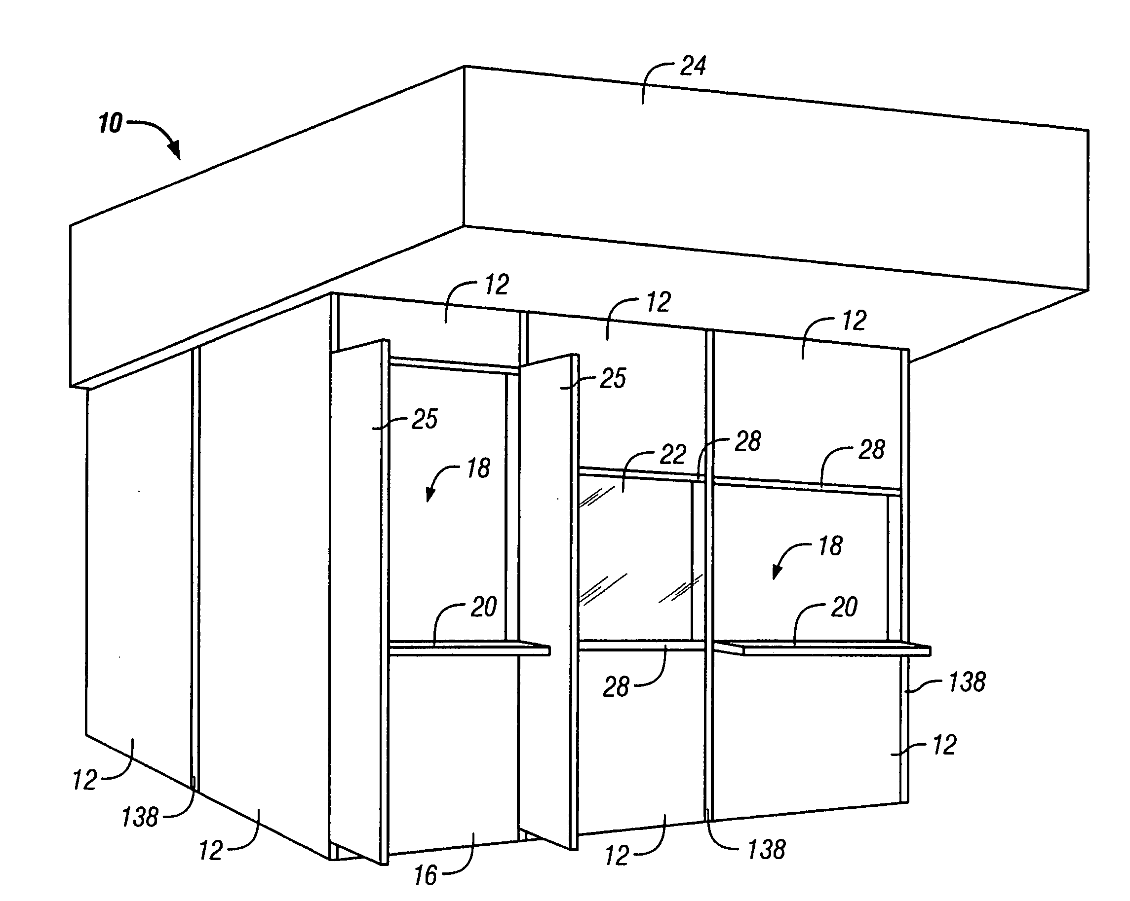
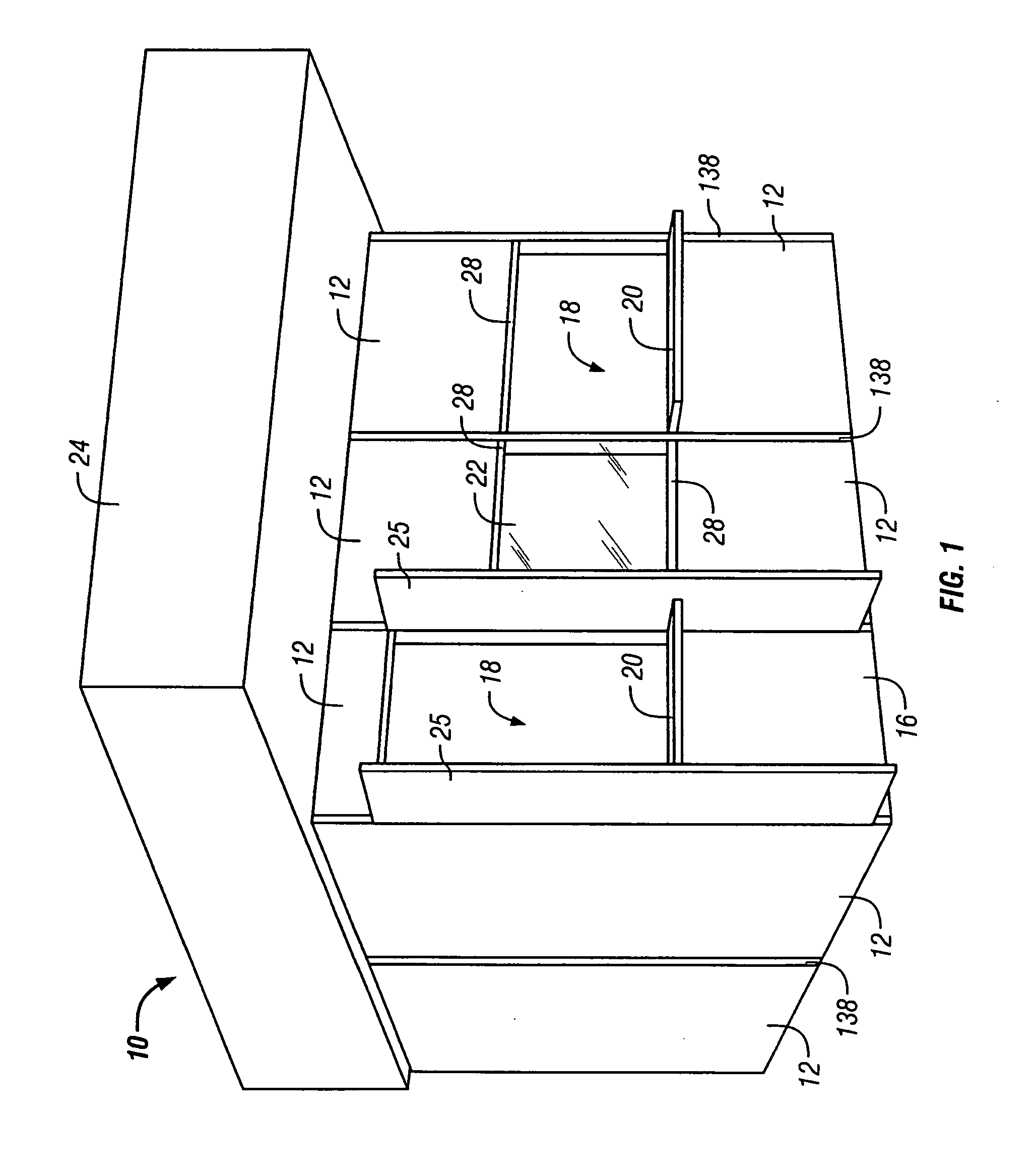
[0066] A modular room according to a preferred embodiment of the present invention is shown in FIG. 1, and is indicated generally at 10. In its various embodiments, the modular room 10 of the present invention is located partially or fully in another structure, such as a department store or other type of retail store, a shopping mall, or the like. Although the most preferred embodiments of the present invention are internal with respect to another surrounding structure, it should be noted that one or more walls of the room 10 can define an external wall of such a structure in other embodiments.

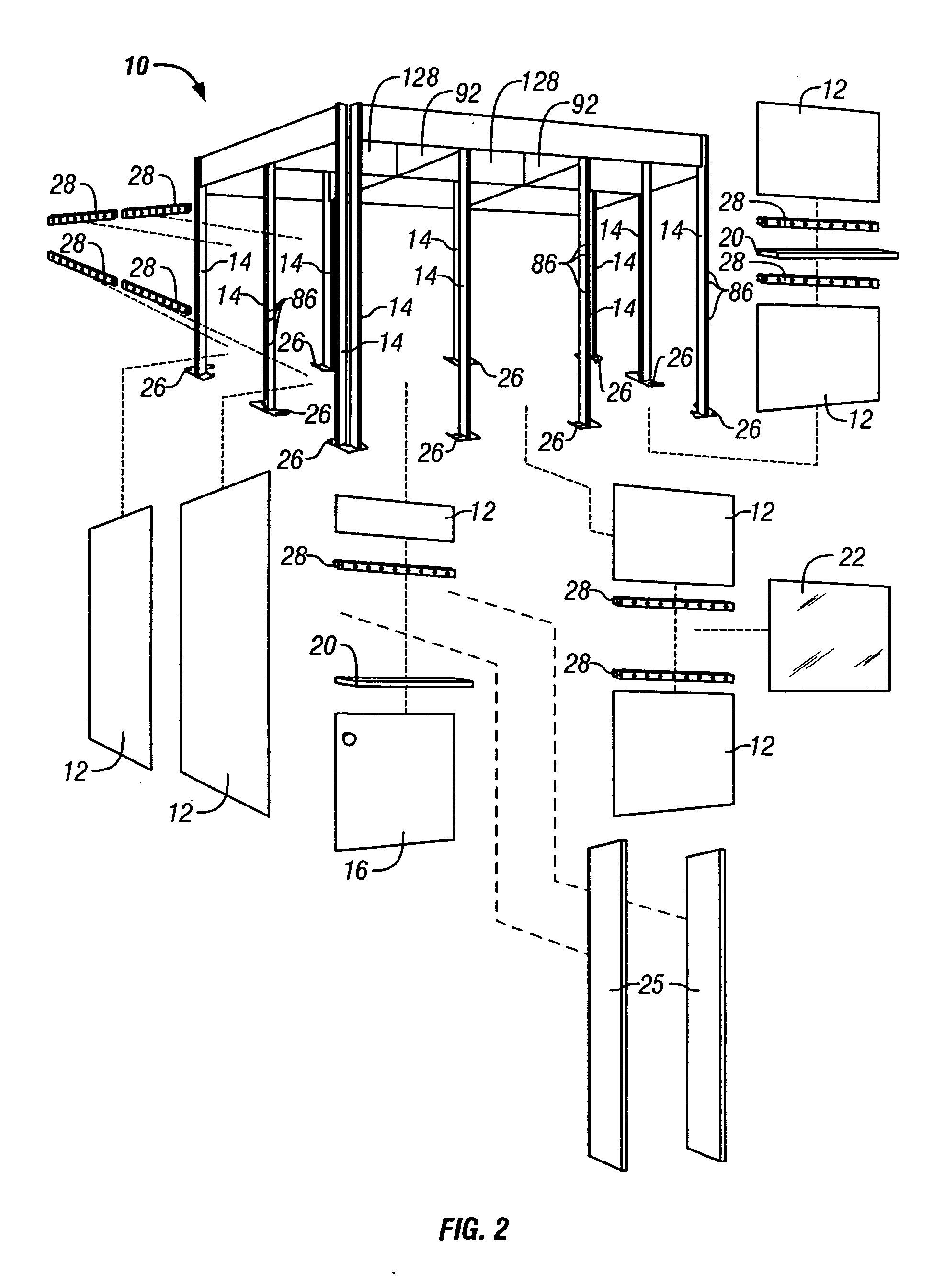
[0067] With continued reference to FIG. 1, the modular room 10 employs elements and structure that permit rapid assembly of the room 10. The room 10 preferably employs a number of standardized components and assemblies enabling such assembly. As described in greater detail below, these components and assemblies can include anchor plates, primary vertical posts or “uprights” connected to the a...


PUM


Abstract

Some embodiments of the present invention employ a modular room including a plurality of modular room components (e.g., anchor assemblies, upright assemblies, etc.). These anchor assemblies and upright assemblies can take different forms permitting assembly of a modular room or modular structure in different manners, and in some cases provide for interchangeable interior and exterior wall panels and components. In some embodiments, a bracket assembly is coupled to an substantially vertical elongated upright for improved strength and stability. Preferably, the anchor assembly has a base plate with at least one edge at an angle with respect to the rest of the base plate for additional strength. If desired, the vertical position of the upright with respect to the base plate can be adjusted. In some embodiments, one or more overhead trusses are used to stabilize the walls of a modular room.

Description

CROSS-REFERENCE TO RELATED APPLICATIONS [0001] This is a continuation and claims priority to U.S. patent application Ser. No. 10 / 702,339 filed on Nov. 6, 2003 and issued as U.S. Pat. No. 7,165,360 on Jan. 23, 2007, and also claims priority to international Patent App. No. PCT / US02 / 14353 filed on May 6, 2002, and U.S. provisional Patent App. Ser. No. 60 / 289,263 filed on May 7, 2001, the entire contents of which are incorporated herein by reference.FIELD OF THE INVENTION [0002] The present invention relates to room structures, and more particularly to modular rooms and modular room structures, methods for assembling such rooms and structures, modular room and structure components, and methods of assembling such components. BACKGROUND OF THE INVENTION [0003] Modular rooms and modular room structures are becoming increasingly attractive for use in a variety of consumer markets due to the modularity and design flexibility of such rooms and room structures. Modular rooms are typically emp...

Claims


Application Information

Patent Timeline
Patent Type & Authority Applications(United States)
IPC IPC(8): A47F10/00E02D27/42E04BE04B2/74E04H1/00E04H1/12E04H3/00E04H5/00E04H6/00E04H12/22E04H14/00
CPCE04B2/7433E04B2002/7483E04H12/2276E04H1/125E04B2002/7487
Inventor THOMPSON, STEVEN C.
Owner L & P PROPERTY MANAGEMENT CO
Why Eureka
Try Eureka