Gear Box Arrangement

Inactive Publication Date: 2007-08-23
DEERE & CO
View PDF8 Cites 26 Cited by
  • Summary
  • Abstract
  • Description
  • Claims
  • Application Information

AI Technical Summary

Benefits of technology

[0005]According to the present invention, there is provided an improved gearbox a

Problems solved by technology

If no lubricant drains from that closure plug, then there is

Method used


Image

  • Gear Box Arrangement
  • Gear Box Arrangement
  • Gear Box Arrangement

Examples


Example

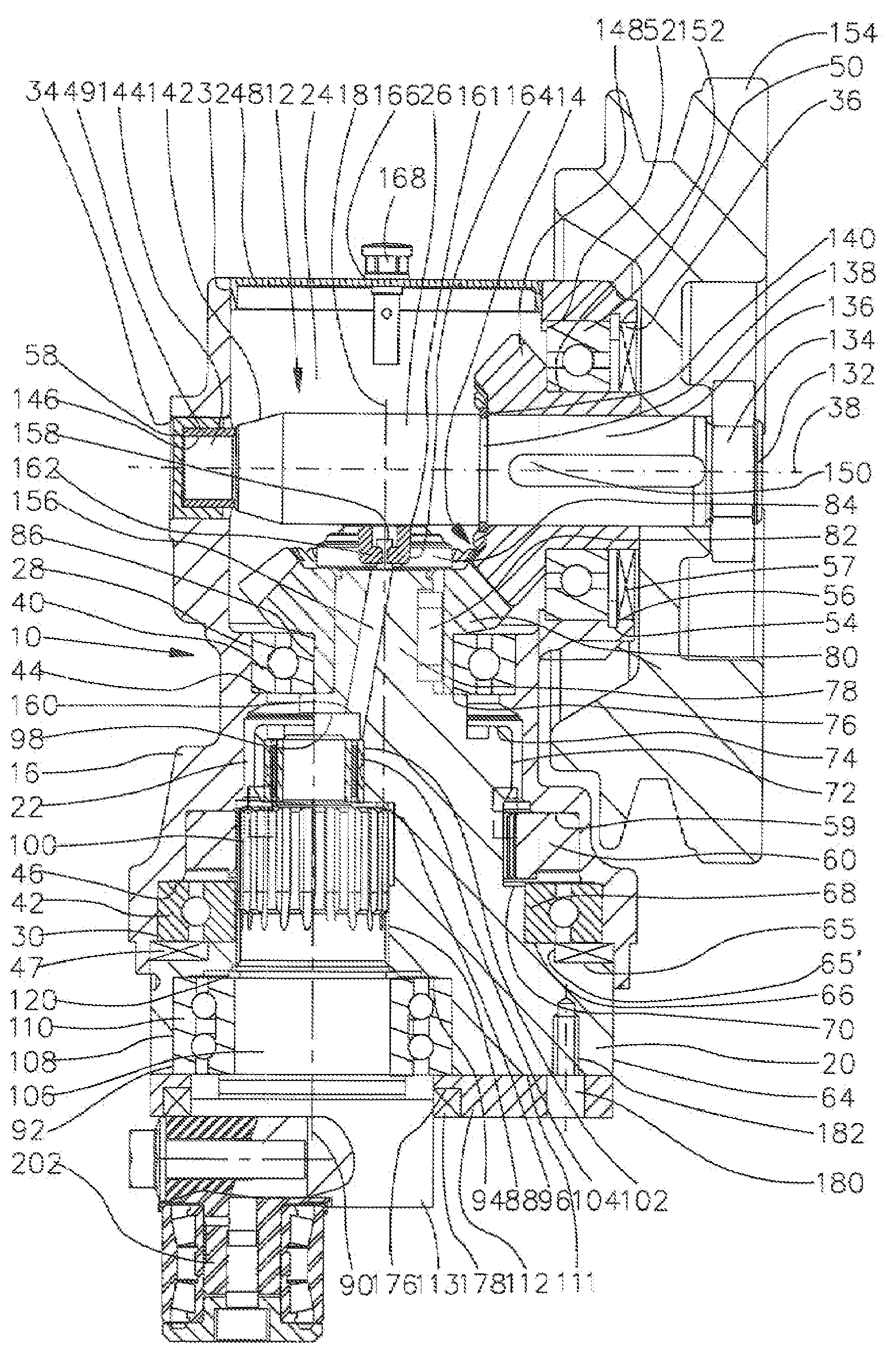
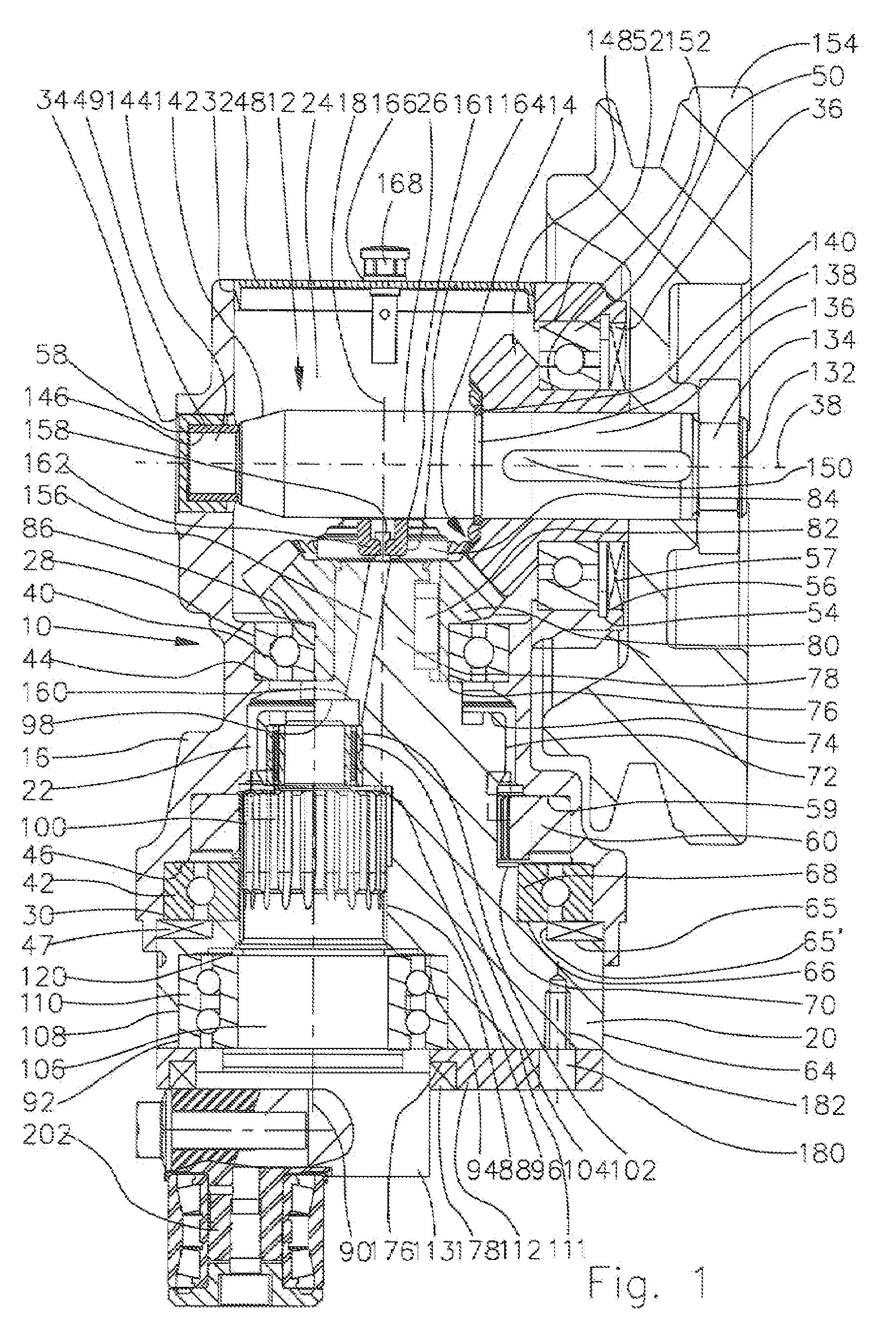
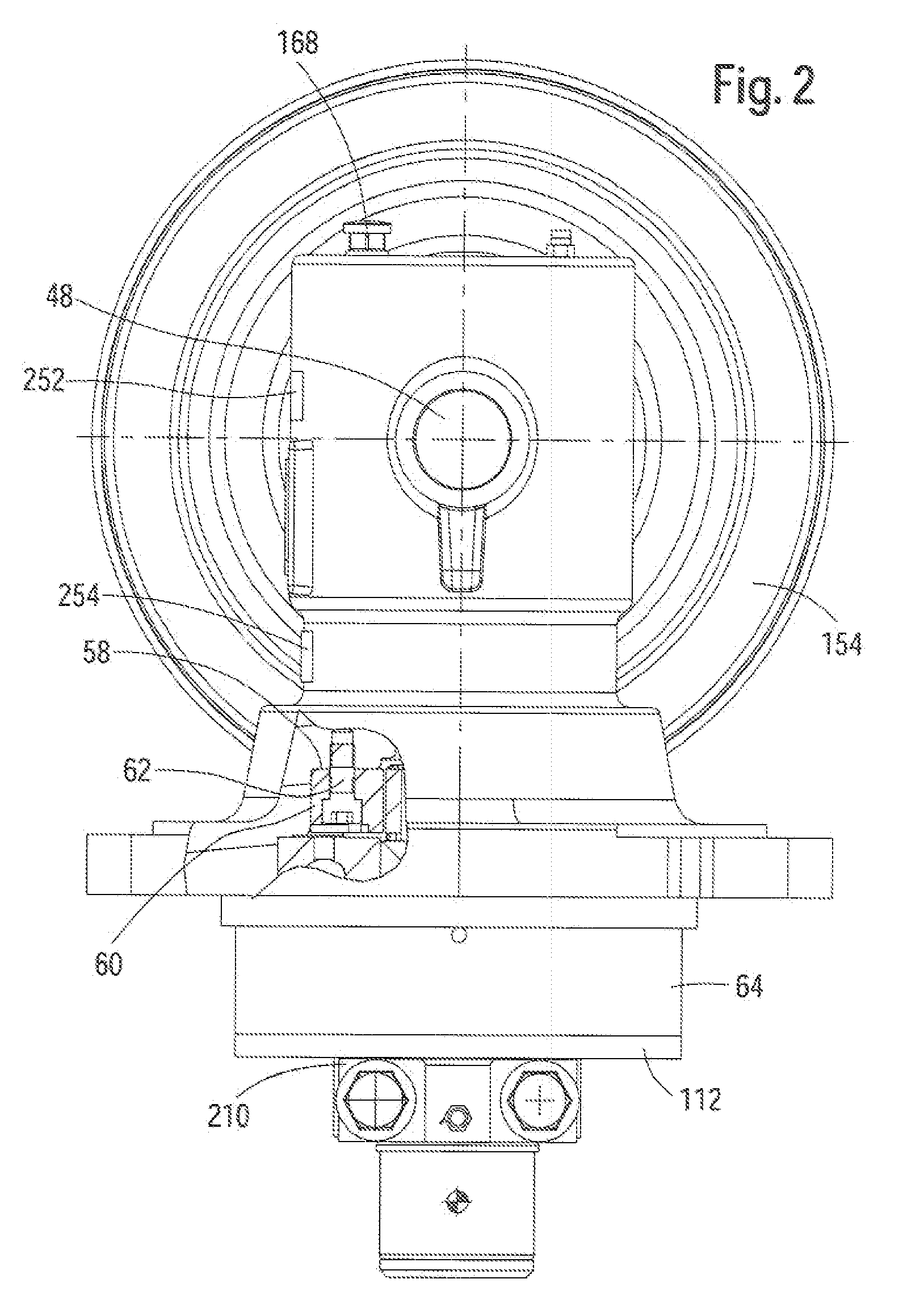
[0038]FIGS. 1 through 3 show a gearbox arrangement 10 constructed in accordance with the present invention, with a gearbox chamber 12 of an angle gearbox 14 being surrounded by a housing 16. The gearbox housing 16 extends generally rotationally symmetrical along an axis of rotation 18 of a first shaft 20, where the axis of rotation 18 defines the longitudinal direction of the gearbox arrangement 10. the gearbox chamber 12 is subdivided into a first gearbox chamber region 22, that generally surrounds the first shaft 20, and a second gearbox chamber region 24, that generally surrounds a third shaft 26 arranged transverse to the longitudinal direction. The gearbox chamber regions 22, 24 are configured as adjoining each other in the longitudinal direction and are provided with a common cylindrical transition region 28, that is arranged approximately in the center of the longitudinal extent of the gearbox housing 16 and coaxially to the axis of rotation 18, and through which an axial con...


PUM


Abstract

A gearbox arrangement includes a gearbox housing, a first shaft supported in bearings in the housing, the first shaft containing a cavity which extends eccentrically to the axis of rotation of the first shaft, a second shaft supported in the cavity for rotation and having an end region projecting from the cavity and being provided with gear teeth, and a third shaft supported in the gear box housing for rotation, with the axis of rotation of the third shaft cooperating with the axis of rotation of the first shaft to define a plane. Leakage of lubricant from the housing is prevented by fastening a plate to the first shaft so as to prevent axial movement of the second shaft while containing an opening for the end region of the second shaft. Sealing devices are provided for all of the openings of the gearbox housing as well as for the opening in the plate in order to prevent the escape of lubricant from the gearbox housing.

Description

FIELD OF THE INVENTION[0001]The invention concerns a gearbox arrangement with a gear box housing, a gearbox chamber enclosed by the gearbox housing, a first shaft supported in bearings in the gearbox housing, a cavity configured eccentrically to the axis of rotation with the center of gravity of its cross section, a second shaft supported in bearings, free to rotate, in the cavity of the first shaft which is provided with at least one area of gear teeth and a shaft end section projecting axially out of the cavity of the first shaft a, and a third shaft supported in bearings in the gearbox housing whose axis of rotation extends at an angle to the plane lying on the axis of rotation of the first shaft.BACKGROUND OF THE INVENTION[0002]Gearbox arrangements are known in the state of the art that are provided with gear rations arranged at angles to each other with gearbox shafts arranged within each other. Gearbox arrangements with gearbox shafts arranged within each other represent, amon...

Claims


Application Information

Patent Timeline
IPC IPC(8): F16P1/00G05G25/00F16H57/02F16H57/021F16H57/022F16H57/029F16H57/04
CPCA01D69/06F16H1/203F16H21/18F16H21/365F16H57/021Y10T74/2191F16H57/029F16H2057/02056F16H2057/0221A01D34/30F16H57/022
Inventor MARTINEZ, MONICA GIL
Owner DEERE & CO
Why Eureka
Try Eureka