Electric power tool

Inactive Publication Date: 2007-08-23
MATSUSHITA ELECTRIC WORKS LTD
View PDF11 Cites 31 Cited by
  • Summary
  • Abstract
  • Description
  • Claims
  • Application Information

AI Technical Summary

Benefits of technology

[0027]In accordance with the embodiment of the present invention, by controlling the motor through monitoring the temperature of the battery unit

Problems solved by technology

In comparison with the conventional Ni—Cd and Ni-MH storage batteries, the Li ion battery tends to suffer a greater reduction in life if its temperature becomes high.
Further, especially when the

Method used


Image

  • Electric power tool
  • Electric power tool
  • Electric power tool

Examples


Embodiment Construction

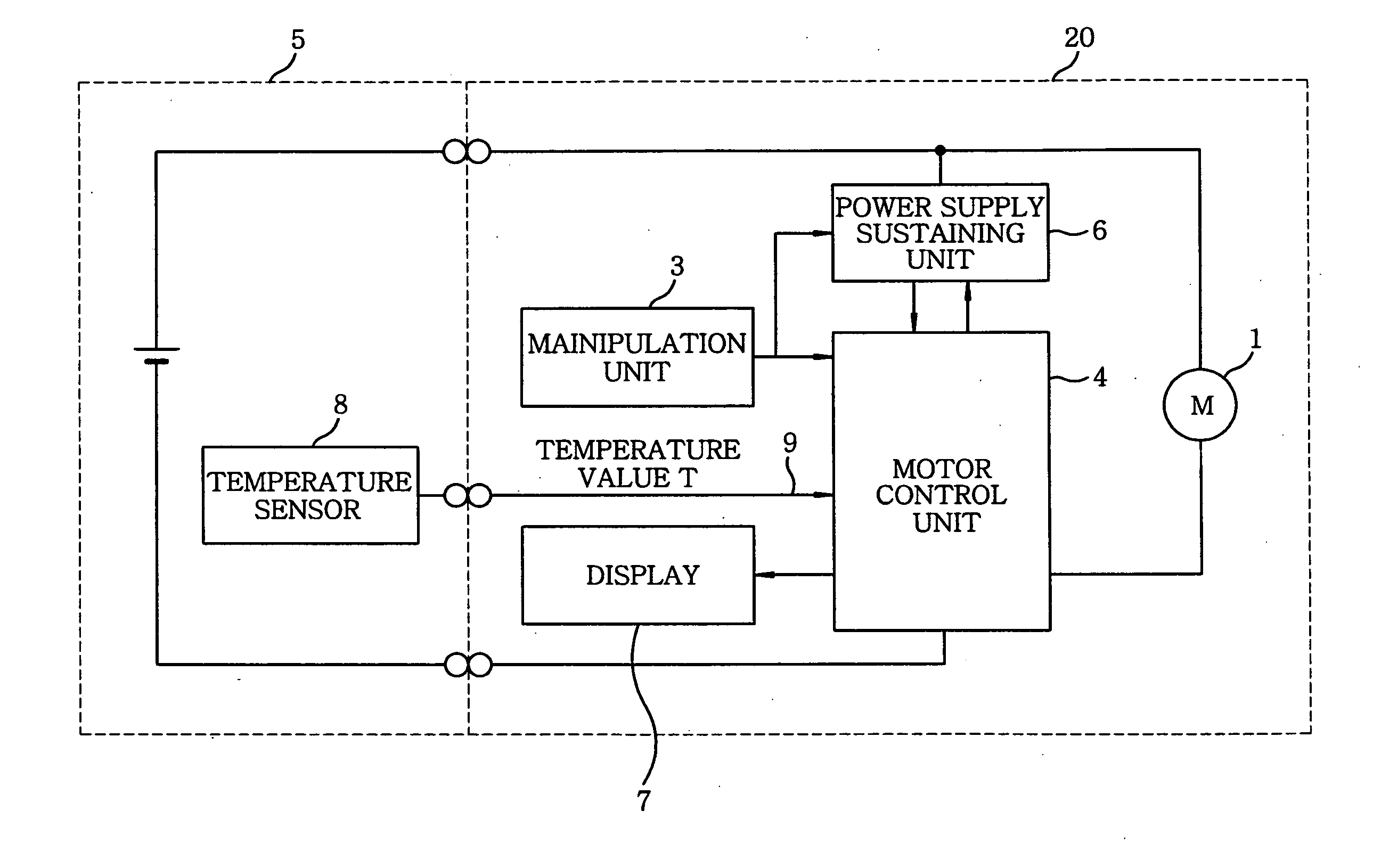
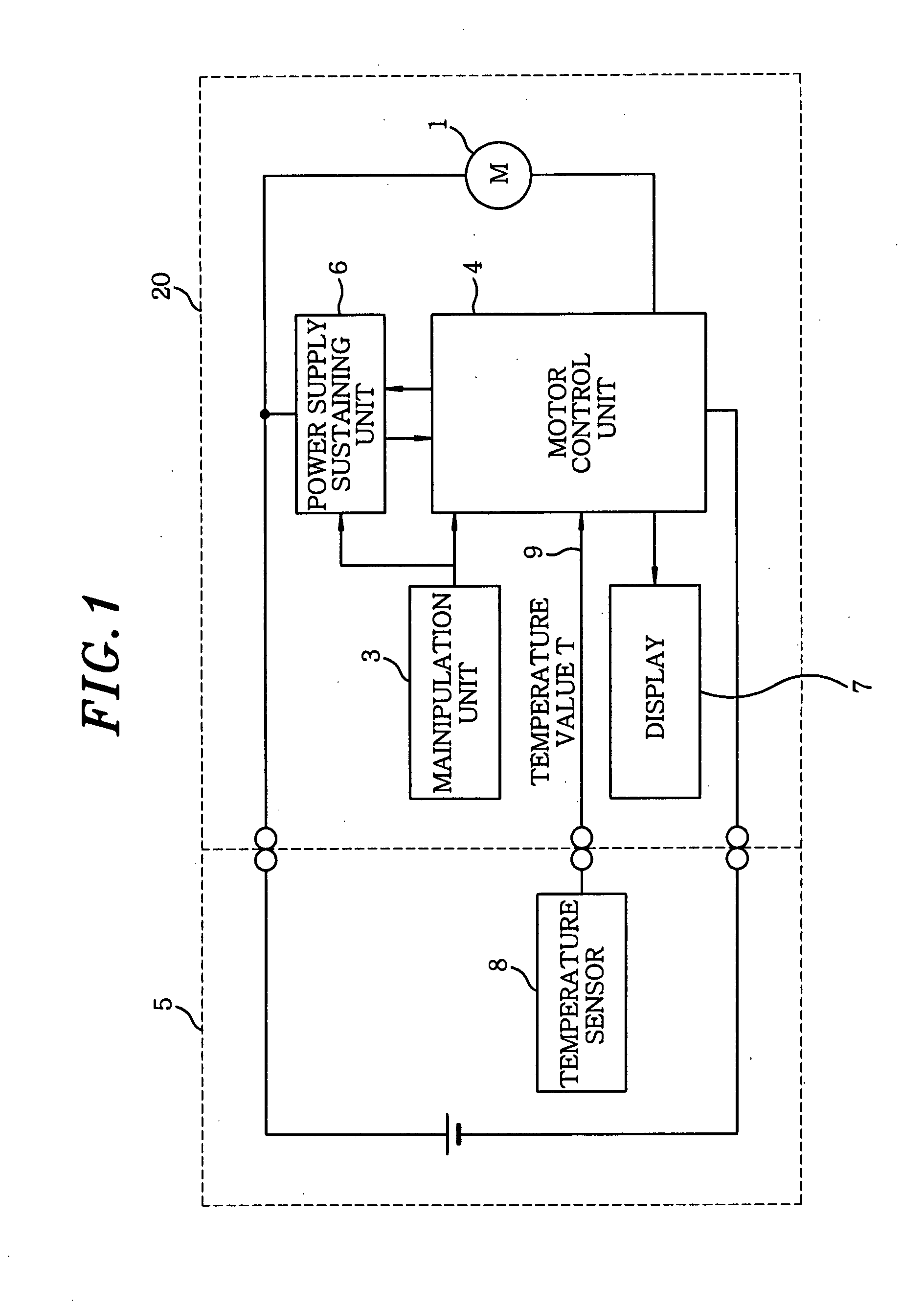
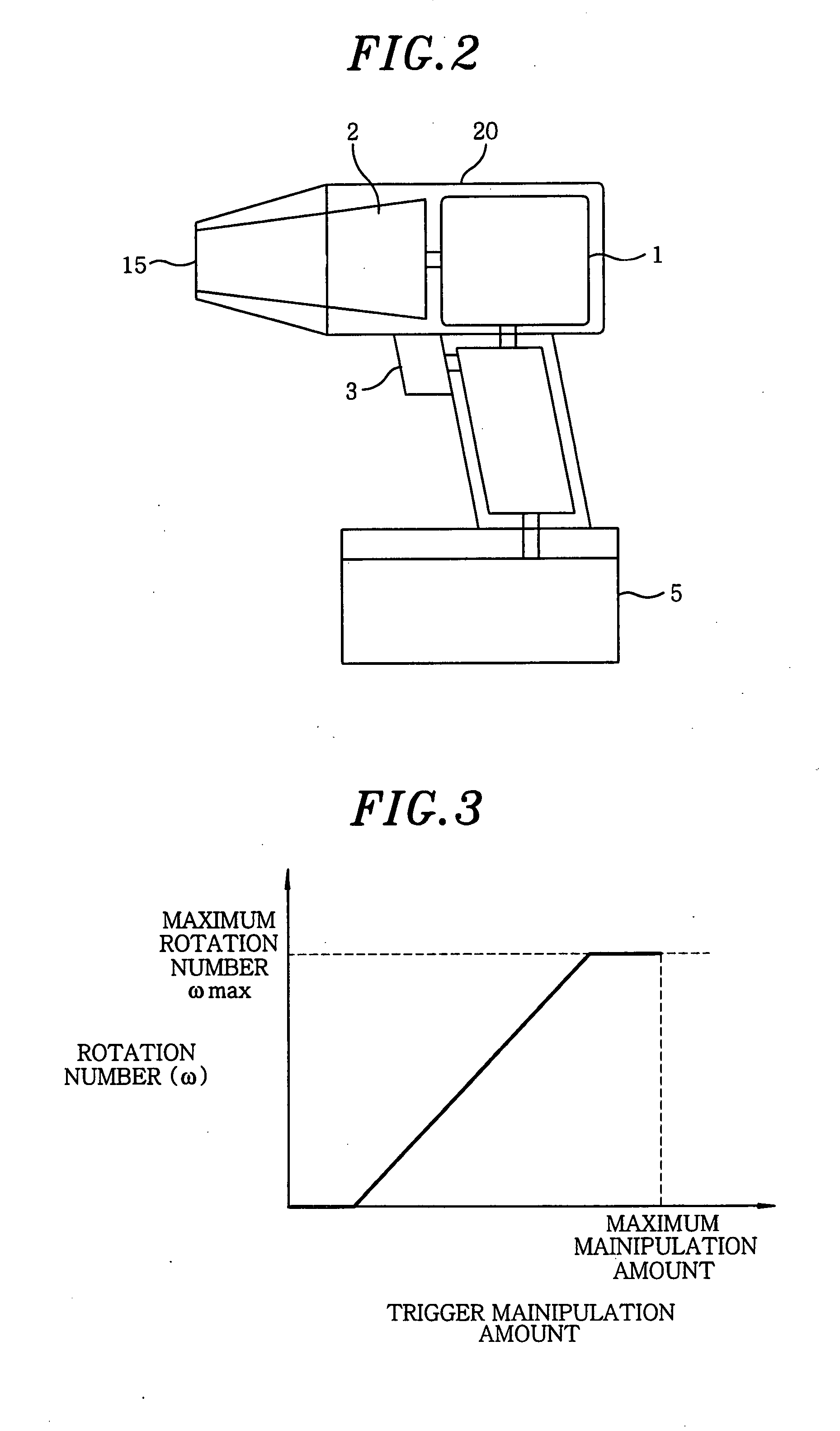
[0039]Hereinafter, embodiments of the present invention will be described with reference to the accompanying drawings. FIGS. 1 and 2 illustrate schematic configurations of an electric power tool in accordance with a first embodiment of the present invention. The electric power tool includes, in a main body 20 thereof, a motor 1; a driving force transmission mechanism 2 for transmitting a rotational driving force of the motor 1; and a motor control unit 4 for controlling a power supply to the motor 1.

[0040]The driving force transfer mechanism 2 is, for example, a screw-fastening mechanism configured with, e.g., a speed reducer with a torque limiting function or an impact generating function for generating a rotary power by repeatedly throwing a hammer to an anvil. The driving force transmission mechanism 2 transmits the rotational driving force of the motor 1 to an output shaft 15 located at a leading end of the main body 20.

[0041]A manipulation unit 3 that is, for example, a trigger...


PUM


Abstract

An electric power tool includes a motor; a battery unit for supplying an electric power for driving the motor; a driving force transmission mechanism for transmitting a driving force of the motor; a manipulation unit for receiving input data including a rotation number and an on/off manipulation of the motor; a motor control unit for controlling the motor based on the input data from the manipulation unit; and a temperature sensor for detecting a temperature of the battery unit as a temperature value. If the temperature value detected by the temperature sensor while being operated in an normal operation mode is higher than or equal to a first abnormal temperature value, the motor control unit determines that the battery unit is in an abnormal state, and converts an operation mode of the motor to a limited operation mode in which a rotation of the motor is stopped or suppressed.

Description

FIELD OF THE INVENTION[0001]The present invention relates to an electric power tool which drives a motor therein to be rotated by an electric power supplied from a battery unit.BACKGROUND OF THE INVENTION[0002]Conventionally, there is known an electric power tool including a motor; a battery unit for supplying an electric power for driving the motor; a driving force transmission mechanism for transmitting a driving force of the motor; a manipulation unit for receiving input data including an on / off manipulation and a rotation number of the motor inputted; and a motor control unit for controlling the motor based on the input data from the manipulation unit.[0003]As the above-mentioned battery unit, a Ni—Cd battery and a Ni-MH battery have been widely used. However, a Li ion battery, which is light in weight and large in capacity, is winning popularity in recent years. In comparison with the conventional Ni—Cd and Ni-MH storage batteries, the Li ion battery tends to suffer a greater r...

Claims


Application Information

Patent Timeline
IPC IPC(8): E21B17/22
CPCH02H5/04B25F5/00H02H7/18H02H7/0858
Inventor ARIMURA, TADASHITANAKA, NAOTAKESEKINO, FUMIAKI
Owner MATSUSHITA ELECTRIC WORKS LTD
Why Eureka
Try Eureka