[0008] The invention is accomplished in view of the above problems. An object of the present invention is to provide a transport apparatus which can shorten a time to be required for changing the direction of a carrier.
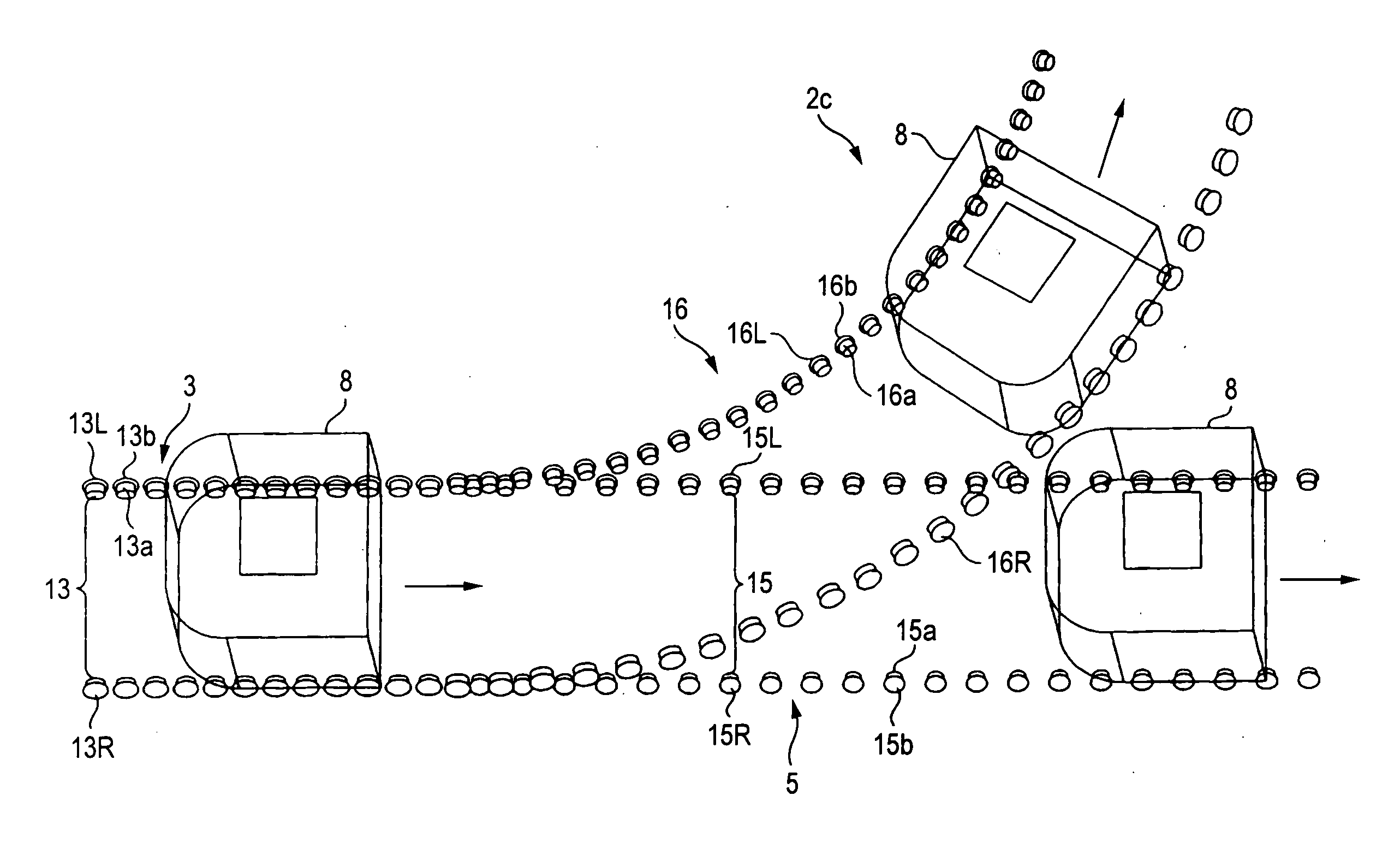
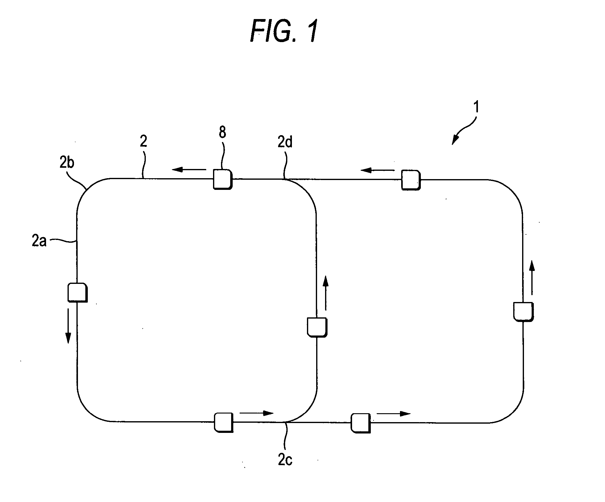
[0013] According to the invention, the switching unit provided at the branch portion performs the switching between the branch track and the linear track so as to guide the article to be transported along one of the branch track and the linear track in accordance with the traveling direction of the article to be transported. Thus, when guiding the article to be transported in the straight line direction and also when guiding the article to be transported so as to change the traveling direction thereof, there is a case that the article to be transported can be transported without being temporarily stopped by merely performing the switching between the branch track and the linear track. Further, since it is not necessary to provide a time for restoring to the original point like the turntable, the time necessary for changing the direction of the article to be transported can be shortened.
[0017] According to the invention, the right side roller has the
diameter different from that of the left side roller. Accordingly, the rotation speed of the roller having the large
diameter becomes faster than the rotation speed of the roller having the small
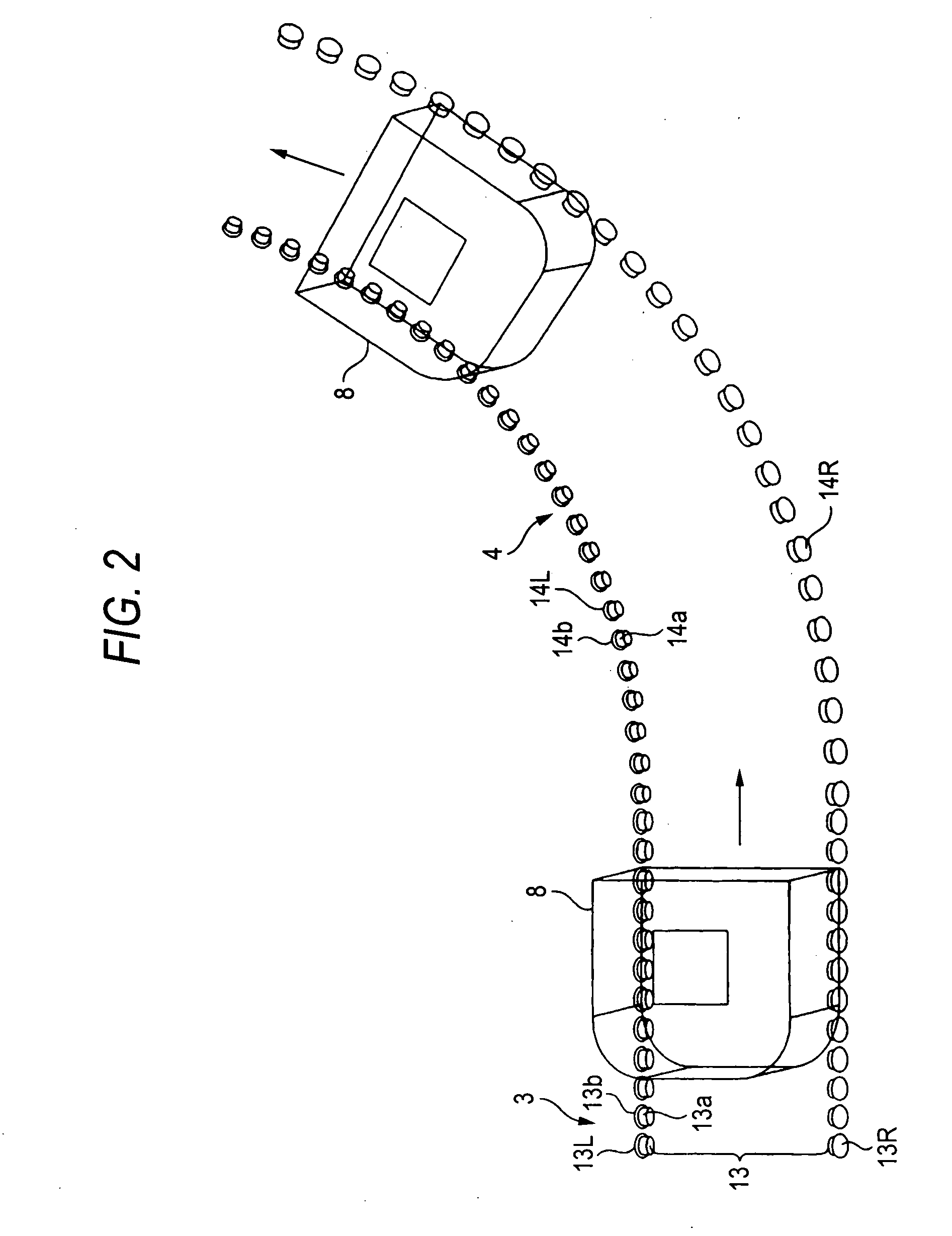
diameter when the both rollers are rotated. Thus, the article to be transported can be transported smoothly while changing the traveling direction thereof, by using the roller having the large diameter as the roller on the outer periphery side, without using a particular mechanism for making the transporting speed of the article to be transported on the outer periphery side faster than the transporting speed of the article to be transported on the inner periphery side. Further, since each of the left side roller and the right side roller has the article to be transported receiving portion of a tapered shape formed by the part of the side surface of the cone, it is possible to suppress to the minimum the generation of dust due to the slip between the article to be transported and the rollers.
[0022] According to the invention, the switching unit provided at the branch portion performs the switching between the branch track and the linear track so as to guide the article to be transported along one of the branch track and the linear track in accordance with the entering state of the article to be transported into the join portion. Thus, when guiding the article to be transported so as to join to the main track from the traveling direction thereof same as the main track and also when guiding the article to be transported so as to join to the main track from the traveling direction of the article different from the main track, there is a case that the article to be transported can be transported without being temporarily stopped by merely performing the switching between the join track and the linear track. Further, since it is not necessary to provide a time for restoring to the origin like the turntable, the time necessary for changing the direction of the article to be transported can be shortened.
[0026] According to the invention, since the right side roller has the diameter different from that of the left side roller, the rotation speed of the roller having the large diameter becomes faster than the rotation speed of the roller having the small diameter when the both rollers are rotated. Thus, the article to be transported can be transported smoothly while changing the traveling direction thereof, by using the roller having the large diameter as the roller on the outer periphery side, without using a particular mechanism for making the transporting speed of the article to be transported on the outer periphery side faster than the transporting speed of the article to be transported on the inner periphery side. Further, since each of the left side roller and the right side roller has the article to be transported receiving portion of a tapered shape formed by the part of the side surface of the cone, it is possible to suppress to the minimum the generation of dust due to the slip between the article to be transported and the rollers.
[0028] According to the invention, the rollers on the outer periphery sides have the flanges on the outer periphery sides thereof respectively. Thus, the flanges can suppress the
centrifugal force, which is generated at the article to be transported when the article to be transported travels while changing the traveling direction thereof.

