Vacuum tray for vacuum packing

a vacuum bag and vacuum technology, applied in the directions of packaging, transportation and packaging, containers, etc., to achieve the effect of convenient vacuum bag vacuum packing, simple structure and smooth vacuum bag vacuum packing

Inactive Publication Date: 2007-08-23
AHN JOON YOUNG
View PDF7 Cites 5 Cited by
  • Summary
  • Abstract
  • Description
  • Claims
  • Application Information

AI Technical Summary

Benefits of technology

[0012] Accordingly, the present invention has been made keeping in mind the above problems occurring in the prior art, and an object of the present invention is to provide a vacuum tray for vacuum packing which makes it possible to put food into a vacuum bag in a single process, and of which a front part has a structure capable of easily discharging air in the vacuum bag to the outside through an opening of the vacuum bag, thus smoothly vacuum-packing the vacuum bag.
[0013] Another object of the present invention is to provide a vacuum tray for vacuum packing in which an airf...

Problems solved by technology

However, because vacuum bags having embossments...

Method used


Image

  • Vacuum tray for vacuum packing
  • Vacuum tray for vacuum packing
  • Vacuum tray for vacuum packing

Examples


first embodiment

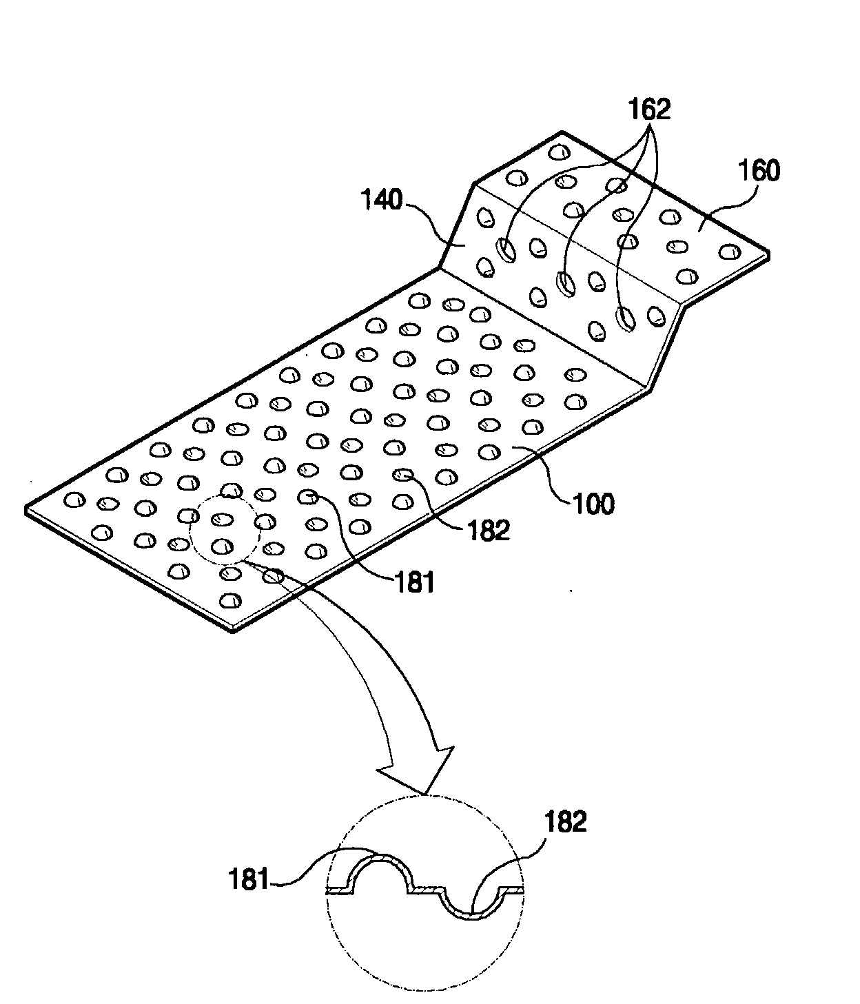
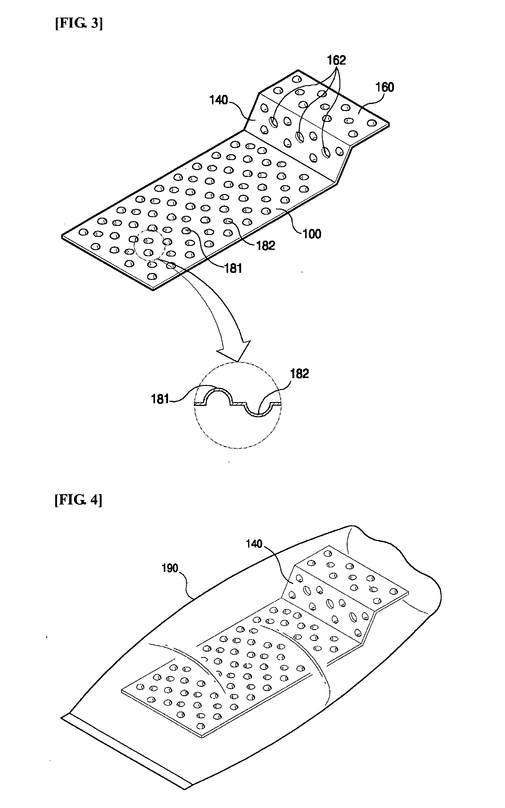
[0031]FIG. 3 shows a vacuum tray for vacuum packing according to a preferred embodiment of the present invention. FIG. 4 is a view showing the vacuum tray which is inserted along with an object into a vacuum bag. As shown in FIG. 3, the vacuum tray for vacuum packing according to the present invention includes a bottom plate 100 which is inserted into a vacuum bag to support thereon an object to be packed; and an inclined plate 140 which is integrally coupled to a front end of the bottom plate 100 and is inclined at a predetermined angle with respect to the bottom plate 100. Embossments such as protrusions 181 and 182 are formed on and under both the bottom plate 100 and the inclined plate 140.

[0032] Such embossments may be formed only on inner surfaces of both the bottom plate 100 and the inclined plate 140, like the protrusions 181 formed on their inner surfaces. Alternatively, the embossments may be formed only on their outer surfaces, like the protrusions 182 formed on their ou...

second embodiment

[0041]FIG. 5 shows an airflow defining part integrated with a vacuum tray such as that shown in FIG. 3.

[0042] Referring to FIG. 5, it is understood that a first airflow defining part 200 is coupled to a front end of an upperplate 160 of the vacuum tray such as that shown in FIG.3. Preferably, the first airflow defining part 200 is integrated with the vacuum tray through an injection molding process. To reduce the material cost and to allow it to be cut easily, the first airflow defining part 200 is tinier than the upper plate 160.

[0043] The first airflow defining part 200 must be made of material which can be thermally bonded to a vacuum bag. The reason is that, when an opening of the vacuum bag is thermal-sealed by a thermal sealing means 50, the first airflow defining part 200 must be thermally bonded to the vacuum bag together.

[0044]FIG. 6 shows a vacuum tray which is not embossed in regions other than a first airflow part 200, unlike the vacuum tray of FIG. 5. In the case tha...

third embodiment

[0052]FIG. 7 shows a coupling of a second airflow defining part 330 to a vacuum tray such as that shown in FIG. 3. A vinyl sheet having embossments is used as the second airflow defining part 330. Furthermore, a piece cut from a typical vinyl bag having embossments maybe used.

[0053] The second airflow defining part 33 is coupled to an upper plate 160 of the vacuum tray by a holder 310. The holder 310 includes a coupling part 311, a support plate 312 and a clamp 313. The coupling part 311 serves to couple the holder 310 to the upper plate 160 of the vacuum tray. As shown in FIG. 12, the coupling part 311 has a U-shaped cross-section. The upper plate 160 is inserted into a hole of the coupling part 311 having the U-shaped cross-section, so that the coupling part 311 is coupled to the upper plate 160.

[0054] The support plate 312 supports thereon the second airflow defining part 330 such as a piece of vacuum bag. The clamp 313 holds the second airflow defining part 330 placed on the s...


PUM


Abstract

The present invention relates to a vacuum tray which is inserted into a vacuum bag and makes it possible for the vacuum bag to be easily vacuumized even if the vacuum bag has no embossments. Particularly, the vacuum tray is characterize in that an airflow defining part (200), which can be thermally bonded to a vacuum bag, is provided at a front end of the vacuum tray so that air in the vacuum bag is easily discharged to the outside through an opening of the vacuum bag. Furthermore, the present invention is characterized in that a cover (400) may be coupled to the vacuum tray, thus preventing appearance of a food from being deformed.

Description

TECHNICAL FIELD [0001] The present invention relates to a vacuum tray for vacuum packing which is inserted into a vacuum bag and makes it possible for the vacuum bag to be easily vacuumized even if the vacuum bag has no embossments. BACKGROUND ART [0002] Generally, vacuum bags are a kind of bag which contains therein objects such as food and is vacuumized by a vacuum packing machine before an opening thereof is sealed, thus keeping the objects in a vacuum state. Of these vacuum bags, there are vacuum bags which have no embossments. However, because vacuum bags having embossments are easily vacuumized, they have typically been used. [0003] As a representative example of such vacuum bags, there is a vacuum bag having embossments which was proposed in Korean Laid-open Publication No. 92-0700998. As shown in FIG. 1, the conventional vacuum bag 21 has embossments 25 which are formed on an inner surface of the vacuum bag 21. The embossments 25 form air discharge passages during a vacuum p...

Claims


Application Information

Patent Timeline
IPC IPC(8): B65D8/04
CPCB65D75/004B65D81/2015B65D81/261B65D81/2038B65D81/2023
Inventor AHN, JOON-YOUNG
Owner AHN JOON YOUNG
Why Eureka
Try Eureka