Method of conveying ceramic moldings

a technology for conveying equipment and ceramic moldings, which is applied in the direction of ceramic shaping equipment, transportation and packaging, manufacturing tools, etc., can solve the problems of rod-like ceramic molding, rod-like ceramic molding for manufacturing the final ceramic molding is extremely soft and weak, and is prone to deformation

Inactive Publication Date: 2007-08-23
DENSO CORP
View PDF19 Cites 8 Cited by
  • Summary
  • Abstract
  • Description
  • Claims
  • Application Information

AI Technical Summary

Benefits of technology

[0045] In such a case, the cell wall arranged in a honeycomb manner is liable to be stra...

Problems solved by technology

In this regard, the rod-like ceramic molding immediately after being extrusion-molded is very soft and weak and easily deformable.
However, there is a problem in the above-mentioned conventional conveying apparatus as described below.
That is, when the rod-like ceramic molding immediately after being extrusion-molded is soft and weak, there is a risk in that the rod-like ceramic molding may deform due to the air stream itself ejected from the inner circumference of the rail.
Thereby, the rod-like ceramic molding for manufacturing the final ceramic molding is extremely soft and weak...

Method used


Image

  • Method of conveying ceramic moldings
  • Method of conveying ceramic moldings
  • Method of conveying ceramic moldings

Examples


first embodiment

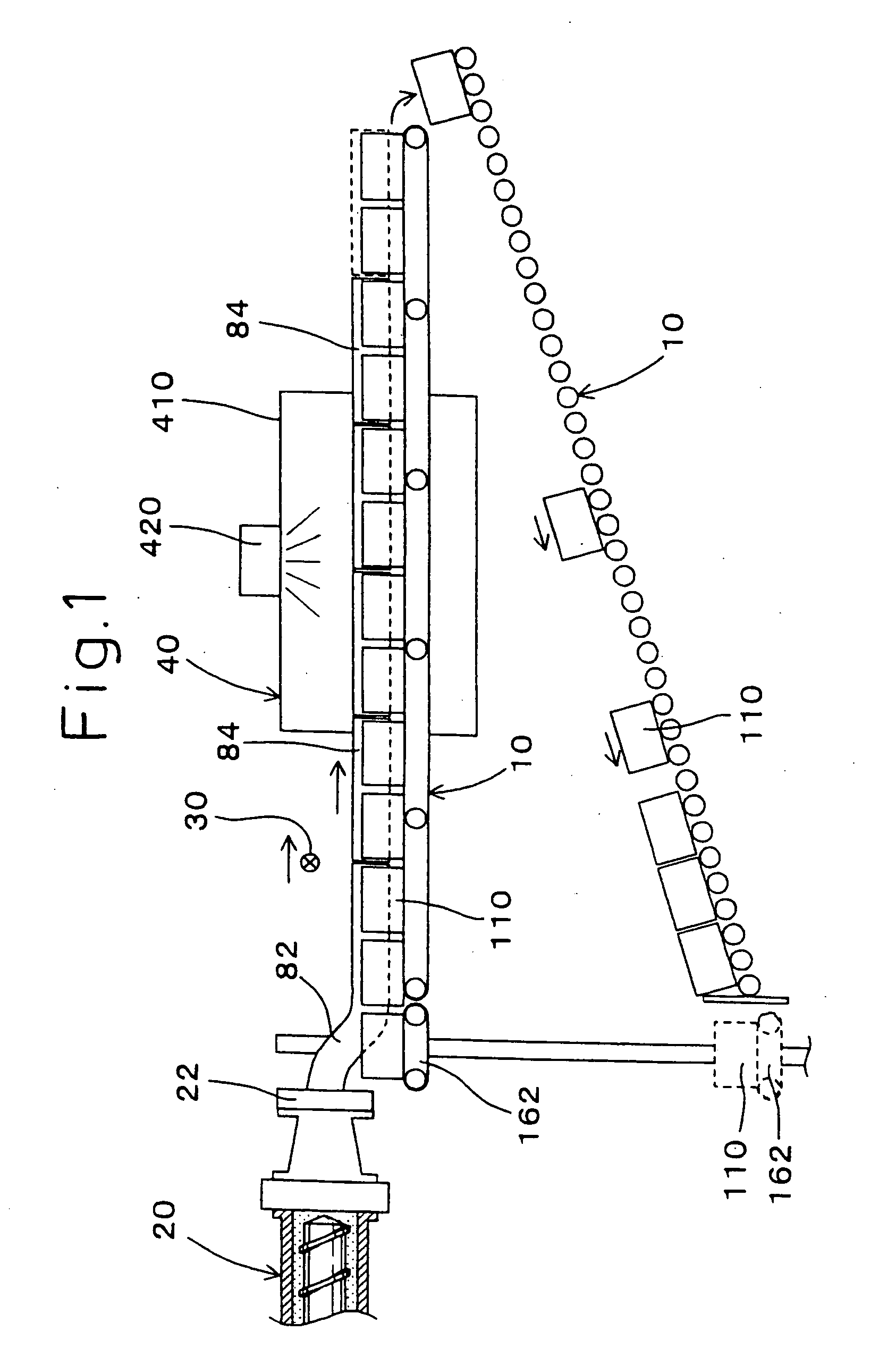
[0062] With reference to FIGS. 1 to 7, an apparatus for conveying ceramic moldings of the present invention will be explained. Initially, a first embodiment will be described below.

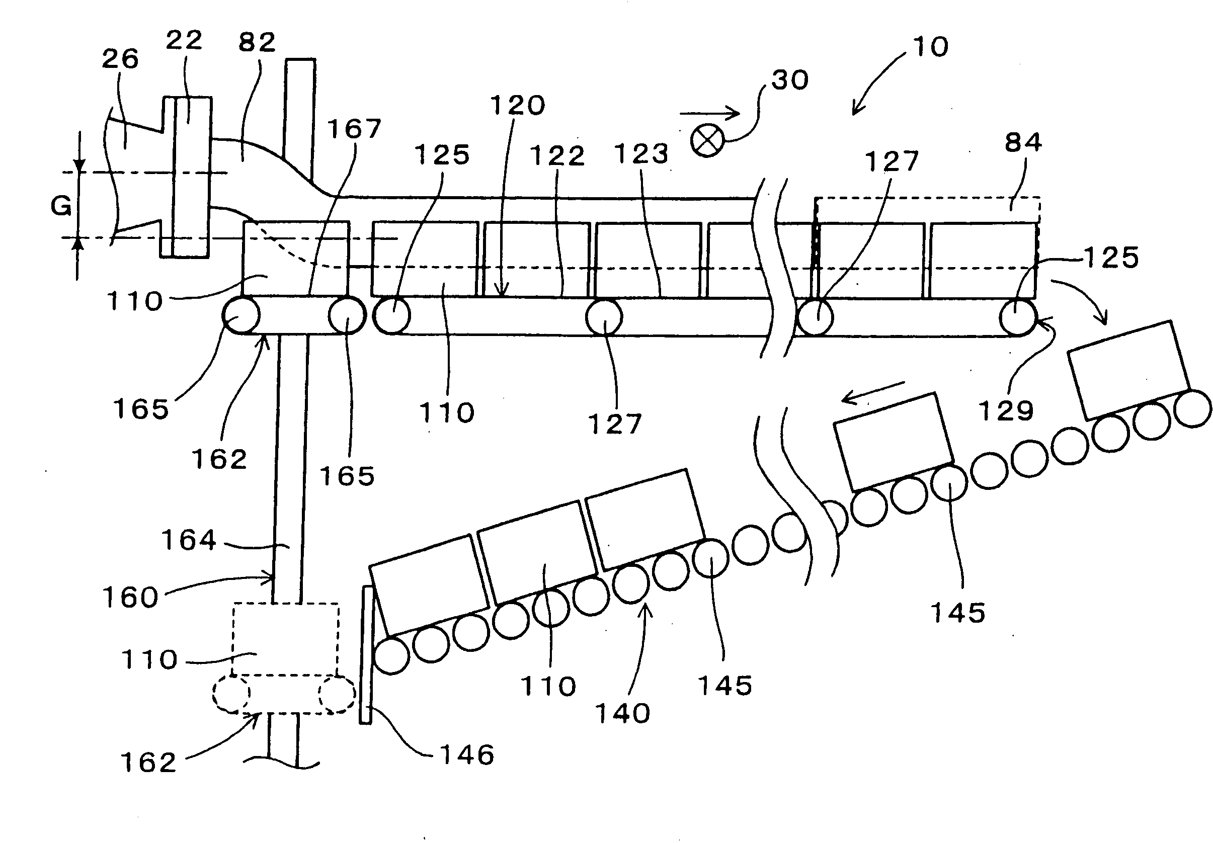
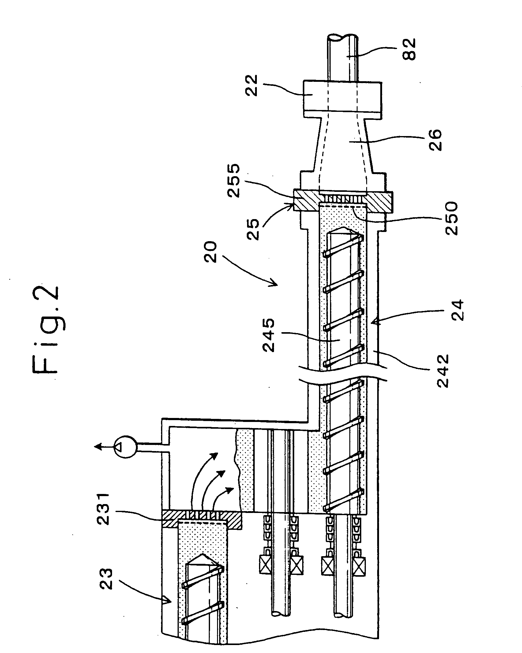
[0063] This embodiment relates to a conveying apparatus 10 for guiding a non-cut rod-like ceramic molding 82 continuously extrusion-molded from a mold 22 and extending from the mold 22 to a cutter 30 in which the rod-like ceramic molding.82 is cut to be ceramic blocks 84, as shown in FIG. 1.

[0064] The conveying apparatus 10 has a plurality of pads 110, each provided with a placement surface to be brought into contact with the outer circumference of the rod-like ceramic molding 82 and place the same thereon. The placement surface of the pad 110 has a length less than a half of an axial length of the ceramic block 84 to be cut from the rod-like ceramic molding 82 in the cutter 30.

[0065] It is arranged that the respective portion in the rod-like ceramic molding 82 to be cut into the ceramic block 84 is sup...

second embodiment

[0119] Next, the present invention will be described below.

[0120] In the second embodiment, a method for supplying the pad is changed while using a conveying apparatus based on that used in the first embodiment.

[0121] As shown in FIG. 8, according to a conveying apparatus 100 in the second embodiment, a belt 222 of a conveyor 220 is formed by joining a plurality of generally flat conveyor plates 224 together, each being larger than a bottom surface of the pad 110, in the conveying direction. To a conveyor surface 223, which is a surface of the conveyor plate 224, one pad 110 is bonded. Also, it is adapted to advance the belt 222 of the conveyor 220 in the extruding direction by the rotation of a rotary roller 225.

[0122] The rod-like ceramic molding 82 continuously extruded from the mold 22 is placed on the pad 110 bonded to the conveyor surface 223.

[0123] According to the conveying apparatus 100 of this embodiment, the operation and effect of the present invention is achievable b...


PUM

PropertyMeasurementUnit
Speedaaaaaaaaaa
Resilienceaaaaaaaaaa

Abstract

The present invention relates to a conveying apparatus for guiding a rod-like ceramic molding, continuously extruded from a mold and extending from the mold while not yet cut, to a cutter for cutting the rod-like ceramic molding into ceramic blocks, each having a predetermined length. The conveying apparatus has pads, each having a placement surface for placing the rod-like ceramic molding while being in contact with the outer circumference of the rod-like ceramic molding, and the placement surface of the pad has an axial length shorter than a half of an axial length of the ceramic block to be cut by the cutter.

Description

[0001] This application is a division of application. Ser. No. 10 / 674,502, filed Oct. 1, 2003, which claims the benefit of priority Japanese Patent Appln. 2002-307490 filed Oct. 22, 2002, the disclosures of each of which are hereby incorporated by reference in this application.BACKGROUND OF THE INVENTION [0002] 1. Field of the Invention [0003] The present invention relates to an apparatus for conveying ceramic moldings obtained by extrusion molding. [0004] 2. Description of the Related Art [0005] In the prior art, there is a horizontal extrusion molding process as one of methods for extruding ceramic moldings. According to this process, a mold is provided at a tip end of an extruder disposed in a horizontal direction (a lateral direction), and ceramic material is continuously introduced into the extruder and extruded from the mold as a continuous rod-like ceramic molding. This continuous rod-like ceramic molding is cut into pieces of a predetermined length to become ceramic blocks. ...

Claims


Application Information

Patent Timeline
IPC IPC(8): B29C47/00B28B3/20B65G15/58B28B11/16B28B13/04B65G35/06B65G49/08
CPCB28B11/241B28B11/243B65G35/06B28B2003/203B28B13/04
Inventor ISHIKAWA, SATOSHIKATOU, HIROMIGOTO, SHOICHI
Owner DENSO CORP
Why Eureka
Try Eureka