Collapsible steering column assembly

a technology of collapsible steering column and assembly, which is applied in the direction of steering parts, vehicle components, transportation and packaging, etc., can solve the problems of steering column collapse and no control over their performance, and achieve the effect of stable e/a process, low cost and maximum simplicity

Active Publication Date: 2007-08-23
STEERING SOLUTIONS IP HLDG +1
View PDF8 Cites 64 Cited by
  • Summary
  • Abstract
  • Description
  • Claims
  • Application Information

AI Technical Summary

Benefits of technology

[0013]The present invention provides the ability to match E / A to load curves of different shapes during collapse of the column. The present invention achieves this result, in either of the two abovementioned embodiemnts with a single, one piece strap that deforms without friction to ensure a stable E / A process with maximum simplicity and low cost.

Problems solved by technology

Such impacts during vehicle collision typically cause the steering column to collapse thereby absorbing energy that may otherwise be transmitted to the operator.
Such energy absorbing (E / A) devices presently have fixed energy absorption capabilities, and offer no control over their performance during the collapse stroke.

Method used


Image

  • Collapsible steering column assembly
  • Collapsible steering column assembly
  • Collapsible steering column assembly

Examples


first embodiment

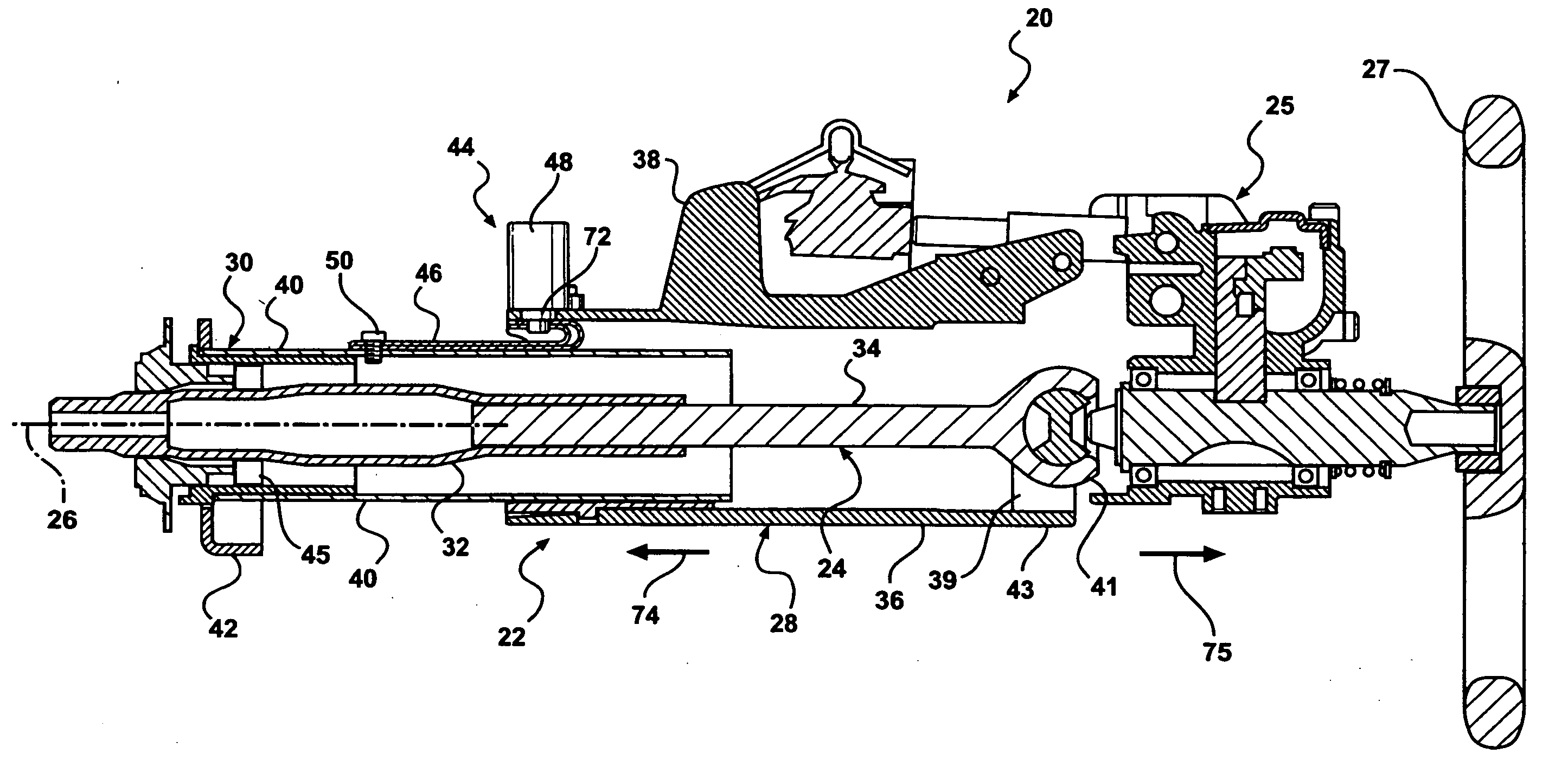
[0034]A variety of sensors (not shown) are responsive to certain sensed conditions relating to driver weight, seat position, whether the driver is belted, and / or vehicle speed. When a pre-specified condition is sensed, the sensor sends an electric signal to the fuse 48 of the E / A device 44 that generally initiates the low load stage of device 44 operation. Upon receipt of the electric signal coupled with a collision event, the fuse 48 fires thereby removing pin 72 from hole 66 just prior to column collapse. Referring now to FIGS. 4-6, strap material free end 62 has two integrally-formed tabs 76 extending in opposite lateral directions. The tabs 76 are seated in a recess 78 generally in portion 36 of outer jacket 28. Recess 78 is partially defined by a pair of shoulders or stops 80 formed in and preferably carried by portion 36 of outer jacket 28. Each stop 80 abuts a respective tab 76 during column collapse. During an activation of the lower load stage of E / A device 44, where the fu...

second embodiment

[0035]Alternatively and as shown in FIG. 7, the assembly is illustrated wherein like components have the same identifying numerals except with the addition of a single prime symbol. For E / A device 44′, strap tabs 76′ may be slidably received in slots 82 formed on opposite lateral sides of recess 78′. Each slot 82 is defined in part by a blind end (not shown) that forms shoulders 80′ against which tabs 76′ abut during collapse of column assembly 20′.

third embodiment

[0036]Referring to FIG. 8, the assembly is illustrated wherein like components have the same identifying numerals except with the addition of a double prime symbol. For E / A device 44″ a hole 84 in the strap 46″ near a material free end 62″ of strap 46″ receives a bolt 86 for securing the free end 62″ to portion 36″ of an outer jacket 28″. With pin 72″ retracted and released from strap 46″ (not shown) during the lower load stage of the E / A device 44″, free end 60″ remains stationary with inner jacket 30″ while the end 62″ of layer 56″ moves generally with the portion 36″ in a direction indicated by arrow 74″. Only the material layer 56″ is stressed and deformed during the lower load stage.


PUM


Abstract

A collapsible steering column assembly preferably has a collapsible steering shaft that extends rotatably along a centerline and a collapsible column that houses and co-extends with the shaft. The column preferably has inner and outer jackets that retract axially to collapse the column. An energy absorbing device has a member engaged between the inner and outer jackets and controls the collapse of the column generally via a high load stage and a low load stage of operation. The member is preferably elongated axially having a distal end that is looped over and spaced radially outward from the remainder of the member. The distal end is attached disengagably to the outer jacket via a pin received in a hole in the distal end and a fuse engaged operably to the pin and attached to the outer jacket.

Description

CROSS-REFERENCE TO RELATED APPLICATIONS[0001]The present application claims priority and all advantages of U.S. Provisional Patent Application Ser. No. 60 / 776,042 filed on Feb. 23, 2006, and is incorporated herein in its entirety.BACKGROUND OF THE INVENTION[0002]1. Field of the Invention[0003]This application relates generally to steering columns, and more particularly to adaptive energy absorbing devices for collapsible steering columns.[0004]2. Description of Related Art[0005]Automotive steering columns are typically equipped with kinetic energy absorption devices to reduce injury of a vehicle operator in the event of a collision that may cause the operator to impact the steering wheel. Such impacts during vehicle collision typically cause the steering column to collapse thereby absorbing energy that may otherwise be transmitted to the operator.[0006]Such energy absorbing steering columns generally include a housing that translates linearly through a collapse stroke during a colli...

Claims


Application Information

Patent Timeline
Patent Type & Authority Applications(United States)
IPC IPC(8): B62D1/00
CPCB62D1/195
Inventor MENJAK, RATKOBOSWELL, KAREN A.FENG, SAINANKELLY, JAMES P.MAGNUS, BRIAN J.STEVERSON, WAYNE M.
Owner STEERING SOLUTIONS IP HLDG
Why Eureka
Try Eureka