Compact Cable Drive Power Sliding Door Mechanism

Active Publication Date: 2007-08-23
MAGNA CLOSURES INC
View PDF21 Cites 18 Cited by
  • Summary
  • Abstract
  • Description
  • Claims
  • Application Information

AI Technical Summary

Benefits of technology

[0011]According to another aspect of the invention, a sliding door drive assembly for moving a sliding door includes an absolute position encoder having sensors for sensing a rotational position of a magnet that rotates no more than once for full travel of the door and thus correlates to a position

Problems solved by technology

The problem with this arrangement is that the cable is pulled at an angle at least toward the end of a windup operation and at the beginning of an unwind operation, so it is fairly common for the cable to jump out of its groove, causing a chafing problem and possibly leading to binding of the cable drum.

Method used


Image

  • Compact Cable Drive Power Sliding Door Mechanism
  • Compact Cable Drive Power Sliding Door Mechanism
  • Compact Cable Drive Power Sliding Door Mechanism

Examples


Embodiment Construction

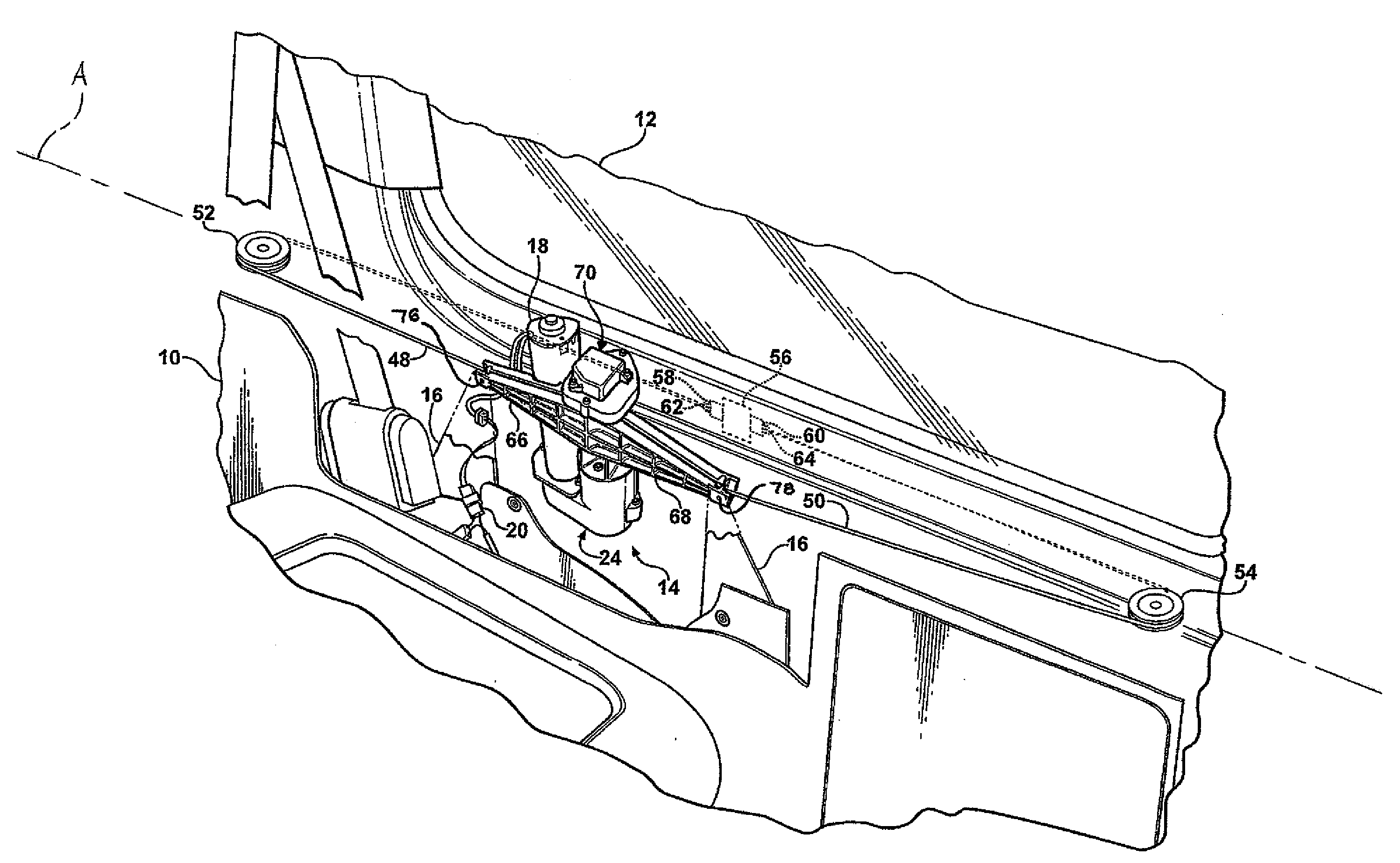
[0022]Referring to FIG. 1, a motor vehicle 10 is shown partially cutaway. The motor vehicle 10 includes a sliding door 12, also partially cutaway. A sliding door drive assembly, generally shown at 14, is mounted to the motor vehicle 10 and is operatively connected to the sliding door 12. Mounting brackets 16 mount the sliding door drive assembly 14 to the motor vehicle 10. It is appreciated that the mounting brackets may actually be another structure of the motor vehicle 10 having functions other than mounting the sliding door drive assembly 14 thereto.

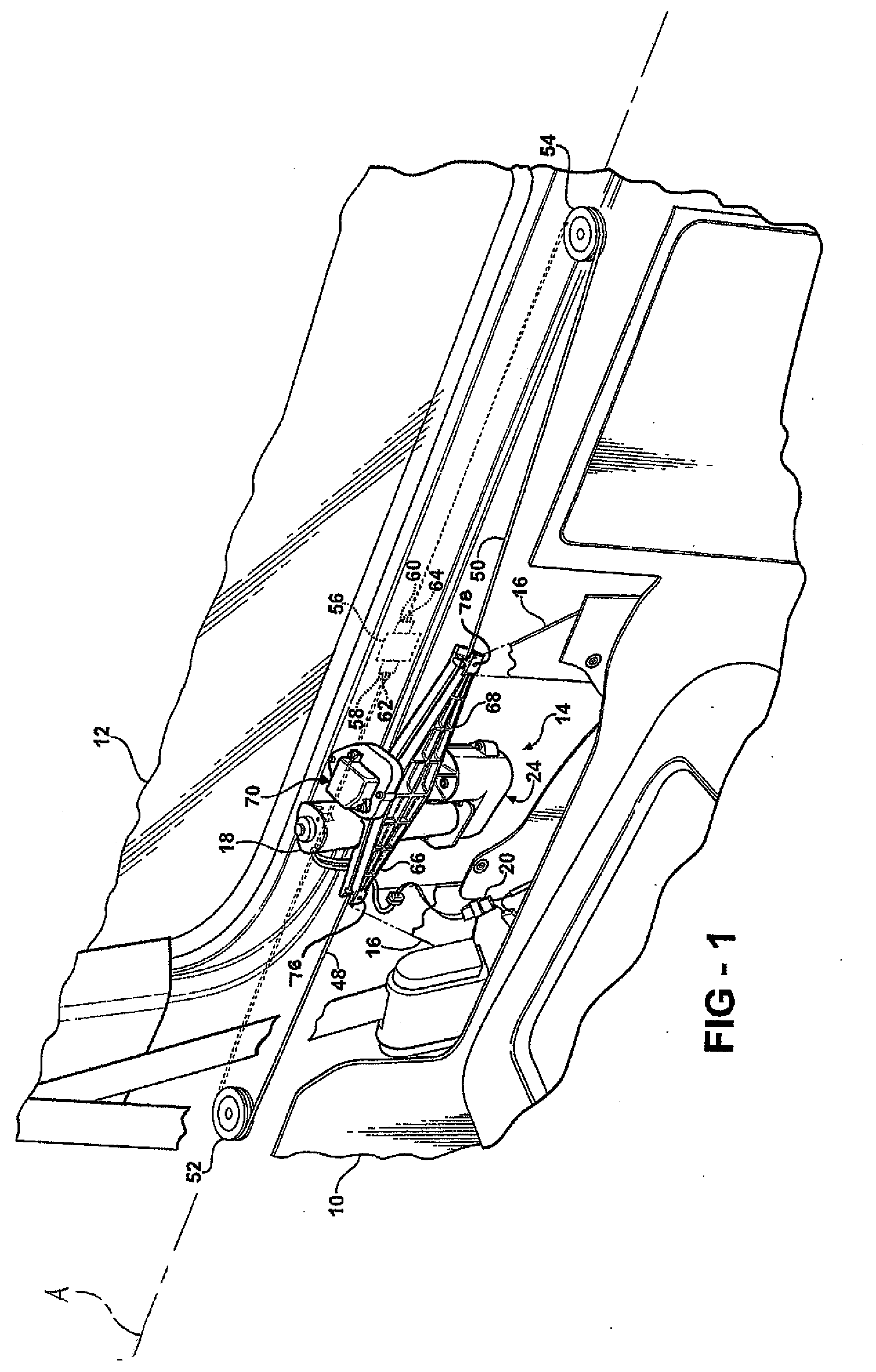
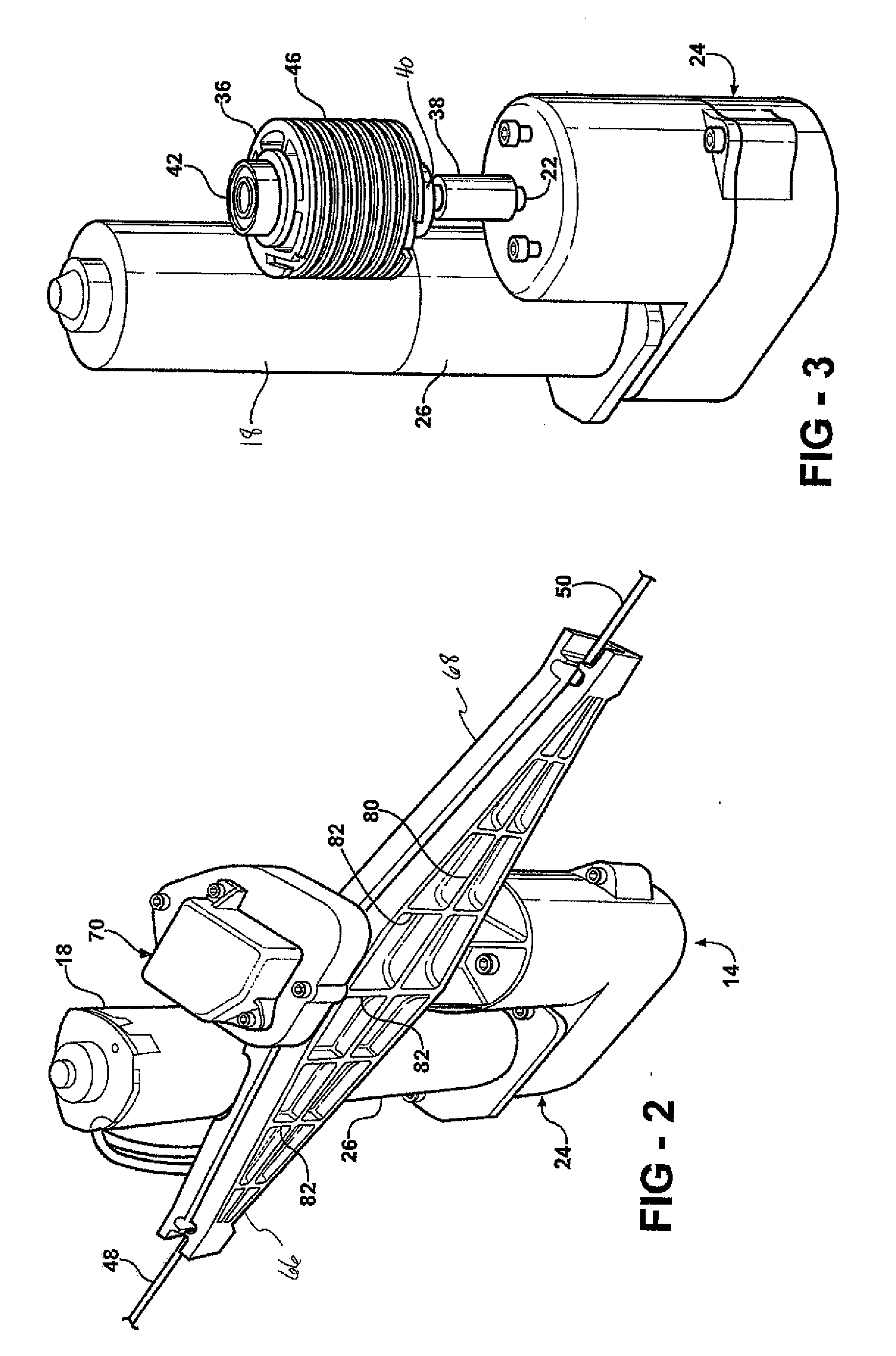
[0023]The sliding door drive assembly 14 includes a motor 18 that is electrically connected to an electric energy source, graphically represented by an electric plug 20. It is contemplated that the motor 18 would operate using electric energy that is standard in a motor vehicle protocol. The motor 18 is bi-directional allowing for rotation of an output shaft 22 (FIG. 3) in two directions. The output shaft 22 is shown as the output sha...


PUM


Abstract

A sliding door drive assembly for a motor vehicle having a sliding door includes a transmission operatively connected to a motor for transmitting a rotating force to an output shaft. A cable drum is fixedly secured to the output shaft and rotates therewith. First and second cables are wound about the cable drum in opposite directions. The first cable extends from the cable drum forward along the sliding door. The second cable extends from the cable drum rearward along the sliding door. Support guides extend tangentially out from the cable drum to guide the first and second cables outwardly and away from the cable drum along a path minimizing frictional forces. Front and rear pulley assemblies are mounted to the motor vehicle and are operatively coupled to the first and second cables between the sliding door drive assembly and the sliding door for tensioning the first and second cables.

Description

CROSS-REFERENCE TO RELATED APPLICATIONS[0001]This is a continuation-in-part of International Application number PCT / CA2006 / 000254, with an international filing date of Feb. 20, 2006.BACKGROUND OF THE INVENTION[0002]1. Field of the Invention[0003]The invention relates to sliding door assemblies for motor vehicles. More specifically, the invention relates to a power sliding door drive assembly for automatically moving a sliding door between an open position and a close position for a motor vehicle.[0004]2. Description of Related Art[0005]In various types of motor vehicles, including minivans, delivery vans, and the like, it has become common practice to provide a vehicle body with relatively large side openings that are located immediately behind front doors and which are opened and closed with a sliding door. The sliding doors are typically mounted with hinges on horizontal tracks on the vehicle body for guided sliding movement between a close position flush with the vehicle body clo...

Claims


Application Information

Patent Timeline
IPC IPC(8): B60J5/00
CPCE05Y2201/654E05Y2201/664E05F15/646E05Y2201/11E05Y2600/40E05Y2900/531E05Y2400/326E05Y2800/232E05Y2800/238E05Y2900/546E05F15/622
Inventor OXLEY, PETER LANCE
Owner MAGNA CLOSURES INC
Why Eureka
Try Eureka