Power supply apparatus

a technology of power supply and power supply, which is applied in the direction of electric variable regulation, process and machine control, instruments, etc., can solve the problem of feedback control standstill

Active Publication Date: 2007-08-23
SANSHA ELECTRIC MFG
View PDF5 Cites 8 Cited by
  • Summary
  • Abstract
  • Description
  • Claims
  • Application Information

AI Technical Summary

Benefits of technology

[0009]The power supply apparatus according to the present invention may be so arranged that, when the switching means is ON, current can flow from the switching means to the transformer, and the control means can control the period during which the switching means is ON, in accordance with the second detection signal.

Problems solved by technology

If such situation continues, the core of the transformer is saturated, resulting in a standstill of the feedback control.

Method used


Image

  • Power supply apparatus
  • Power supply apparatus
  • Power supply apparatus

Examples


Embodiment Construction

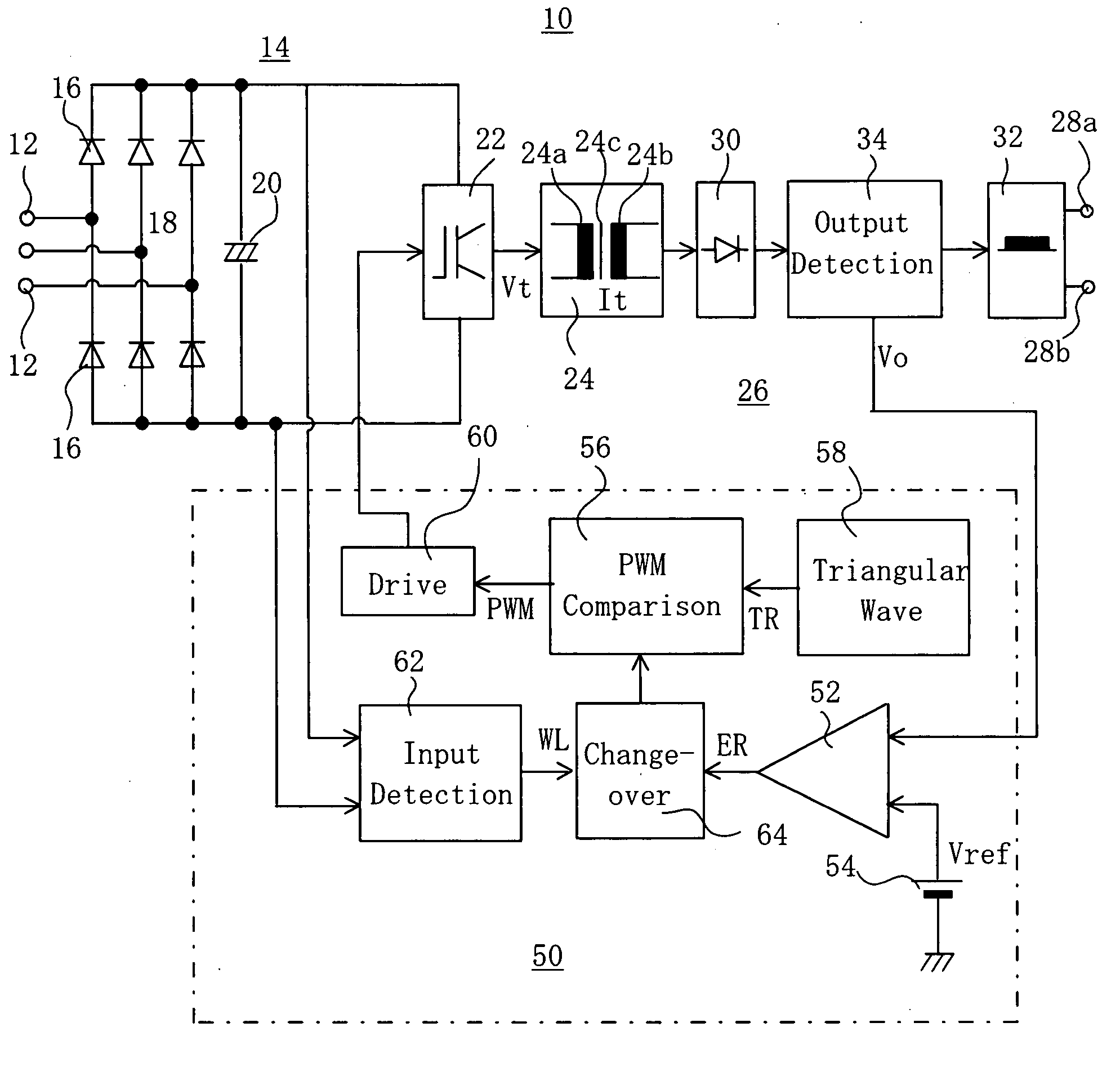
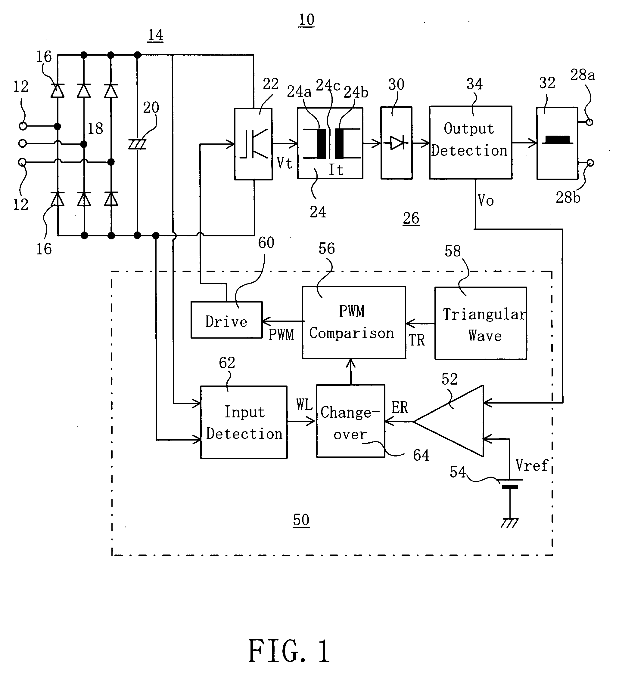
[0016]A power supply apparatus 10 according to the present invention is shown in FIG. 1. The power supply apparatus 10 may be of a portable type. The power supply apparatus 10 has three input terminals 12 through which three-phase AC power is supplied to the apparatus 10 from a commercial power supply. The AC power supplied through the input terminals 12 is coupled to converting means, e.g. an input-side rectifying and smoothing circuit 14, where it is converted to DC power. The input-side rectifying and smoothing circuit 14 includes a three-phase bridge rectifying circuit 18 formed of, for example, six diodes 16, and also a smoothing capacitor 20 for smoothing the output of the three-phase bridge rectifying circuit 18.

[0017]The DC power from the input-side rectifying and smoothing circuit 14 is applied to switching means, e.g. an inverter circuit 22, where it is converted to high-frequency power at a frequency of from, for example, 10 kHz to 100 kHz. The inverter circuit 22 is form...


PUM


Abstract

A rectifying circuit (18) converts inputted AC power to DC power. An inverter circuit (22) converts the DC power to high-frequency power in accordance with a switching control signal applied thereto from a control circuit (50). A voltage transformer (24) voltage-transforms the voltage of the high-frequency power. An output-side rectifying circuit (40) rectifies the voltage-transformed power. An output detecting circuit (34) detects the magnitude of the voltage of the rectified power, and a signal representative of the detected voltage is applied to the control circuit (50). The control circuit (50) generates such a switching control signal as to make the rectified power have a predetermined value. The value of the voltage from the rectifying circuit (18) is detected by an input detecting circuit (62), and a signal representative of the detected voltage is applied to the control circuit (50). The control circuit (50) controls the operation of the inverter circuit (22) in accordance with the detected voltage representative signal from the input detecting circuit (62) and the saturation magnetic characteristic of the voltage-transformer (24).

Description

[0001]This invention relates to a power supply apparatus for arc-utilizing apparatuses such as an arc welder and an arc cutter.BACKGROUND OF THE INVENTION[0002]An example of such power supply apparatuses is disclosed in JP 05-111244 A. The power supply apparatus disclosed in this Japanese publication includes a rectifier which rectifies a commercial AC power supply voltage, and the resultant rectified voltage is applied to a smoothing capacitor through a reactor. A voltage-boosting switching device is connected in the input of the smoothing capacitor. The charging time of the smoothing capacitor is controlled by controlling the ON and OFF times of the switching device. Thus, even when a commercial supply voltage of a different magnitude is applied to the apparatus, the input voltage to the smoothing capacitor can be made substantially constant through the appropriate control of the ON and OFF times of the voltage-boosting switching device. Accordingly, this power supply apparatus ca...

Claims


Application Information

Patent Timeline
Patent Type & Authority Applications(United States)
IPC IPC(8): H05B41/36
CPCH02M7/53871H02M5/458
Inventor ISHII, HIDEOIKEDA, TETSURODANJO, KENZO
Owner SANSHA ELECTRIC MFG
Why Eureka
Try Eureka