Method for providing a polarizing layer on an optical element

a technology of optical elements and polarizing layers, which is applied in the direction of spectacles/goggles, thin material handling, instruments, etc., can solve the problem of not reducing the polarizing efficiency of the layer, and achieve the effect of facilitating a defect-free arrangement of the polarizing layer

Inactive Publication Date: 2007-08-23
ESSILOR INT CIE GEN DOPTIQUE
View PDF4 Cites 53 Cited by
  • Summary
  • Abstract
  • Description
  • Claims
  • Application Information

AI Technical Summary

Benefits of technology

[0016] / a2 / applying a stress to the substance layer when the resilient support is in a planar shape, so that the dichroic compounds produce a polarizing effect of the substance layer for a light beam transmitted through this layer.
[0017]Alternatively, the polarizing layer may consist in a polarizing film which is purchased separately, and then applied on the support. The planar shape of the resilient support during step / a / greatly facilitates again a defect-free arrangement of the polarizing layer on the support.

Problems solved by technology

Because this preforming step is carried out with a resilient support for the polarizing layer, the warping of the support together with the layer does not reduce the polarizing efficiency of the layer.

Method used


Image

  • Method for providing a polarizing layer on an optical element
  • Method for providing a polarizing layer on an optical element
  • Method for providing a polarizing layer on an optical element

Examples


Embodiment Construction

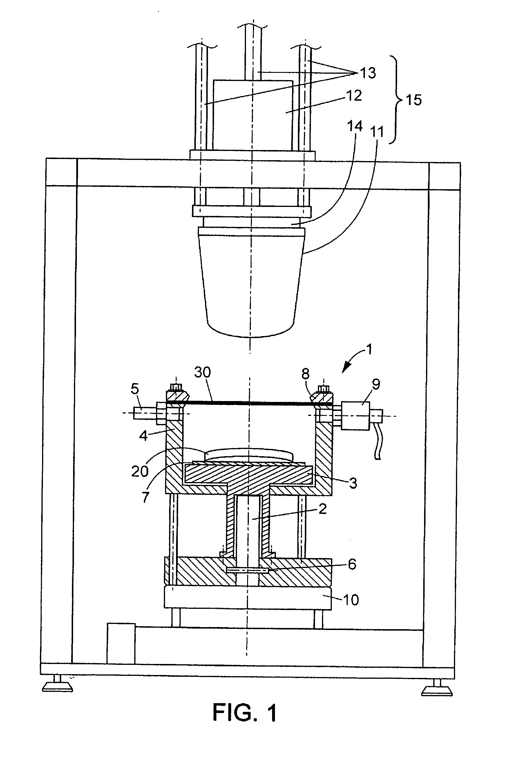
[0029]According to FIG. 1, a device for providing a polarizing layer on an optical element comprises a supporting structure, a vacuum vessel 1 and a stamp 11 vertically movable above the vacuum vessel 1.

[0030]The vacuum vessel 1 may be cylindrically shaped, with a vertical axis. It has a peripheral wall 4 and an aperture in its lower end surface. It is arranged in the supporting structure at a fixed height above a base plate 10. A vertical cylinder 2 is arranged between the base plate 10 and the vacuum vessel 1. A piston 3 is vertically movable over the cylinder 2 and penetrates into the vacuum vessel 1 through the aperture, for lifting a holder 7 inside the vessel. The cylinder 2 is provided with a stop-system 6 which is designed for maintaining the piston 3 in a fixed desired position.

[0031]A fixing ring 8 is arranged on the upper edge of the peripheral wall 4. It is designed for maintaining a peripheral edge of a diaphragm so as to seal the vacuum vessel 1.

[0032]The vacuum vessel...


PUM

PropertyMeasurementUnit
pressureaaaaaaaaaa
fluid pressureaaaaaaaaaa

Abstract

A method for providing a polarizing layer on a curved optical element comprises using a support for temporarily carrying the polarizing layer. The support is resilient so that it can conform with the curved surface of the optical element. An adhesive layer is first deposited on the optical element surface, and the polarizing layer is applied on the adhesive layer by pressing the support. Then, the support is peeled so that the polarizing layer remains on the optical element. The method is compatible with high efficiency polarizing layer based on dichroic compounds.

Description

[0001]The invention relates to a method for providing a polarizing layer on an optical element. It also relates to an optical element with a polarizing layer thereon obtained by implementing such method.BACKGROUND OF THE INVENTION [0002]Methods are already used for applying a film with optical properties onto an eyeglass surface. Because the eyeglass surface is curved, some of these methods comprise a preforming step, so that the film is warped before it is applied on the eyeglass surface. Eyeglasses with optical films which are produced in this way are free of defects and exhibit good optical quality. In particular, their optical power is not altered by the films.[0003]Optical films with different properties are commercially available. In particular, there are films designed for filtering light with respect to a defined wavelength range, or for suppressing a reflected light, or for contrast enhancement, etc. Other films are designed for polarizing a light beam upon transmission. Su...

Claims


Application Information

Patent Timeline
Patent Type & Authority Applications(United States)
IPC IPC(8): B32B33/00G02C7/02
CPCB29C63/0073B29L2011/0016B29D11/0073B29C63/16Y10T428/31504
Inventor MOSSE, HERBERTMUISENER, RICHARD
Owner ESSILOR INT CIE GEN DOPTIQUE
Why Eureka
Try Eureka