Vehicle headlamp

a headlamp and vehicle technology, applied in the field of headlamps, can solve the problems of difficulty in switching to a desired light distribution pattern, adversely affecting the driver, etc., and achieve the effect of improving remote recognizability

Inactive Publication Date: 2007-08-23
KOITO MFG CO LTD
View PDF11 Cites 24 Cited by
  • Summary
  • Abstract
  • Description
  • Claims
  • Application Information

AI Technical Summary

Benefits of technology

[0008]In one aspect, the disclosure relates to a vehicle headlamp capable of improving remote recognizability in a “middle beam” light distribution pattern and capable of switching a light distribution pattern when traveling at high speeds.
[0011]One or more of the following advantages are present in some implementations. The light distribution pattern of “middle beam” can be provided by utilizing, for example, a shade for constituting the “high beam” light distribution pattern. Therefore, the “middle beam” light distribution pattern can be provided by utilizing a region having a high luminous intensity in the “high beam” light distribution pattern as it is, particularly, can improve a luminous intensity of a center region of the light distribution pattern and can improve remote optical recognizability in “middle beam.” By simultaneously carrying out switching of the shade switching means and a control of the leveling means, a number of switching shades necessary for providing different light distribution patterns can be made smaller than the number of the light distribution patterns, and switching of beams can be carried out at high speed.

Problems solved by technology

Therefore, a problem can arise because insufficient remote optical illumination is achieved in the “middle beam” light distribution pattern According to the headlamp of JP-A-2005-259549, a state occurs in which illumination is dark by temporarily switching to a state of “low beam” as a result of a relationship of aligning the shades of the rotary shade, when switched from “middle beam” to “high beam.” Such a state may adversely affect the driver.
This also poses a difficulty in switching to a desired light distribution pattern when traveling at high speed.

Method used


Image

  • Vehicle headlamp
  • Vehicle headlamp
  • Vehicle headlamp

Examples


embodiment 1

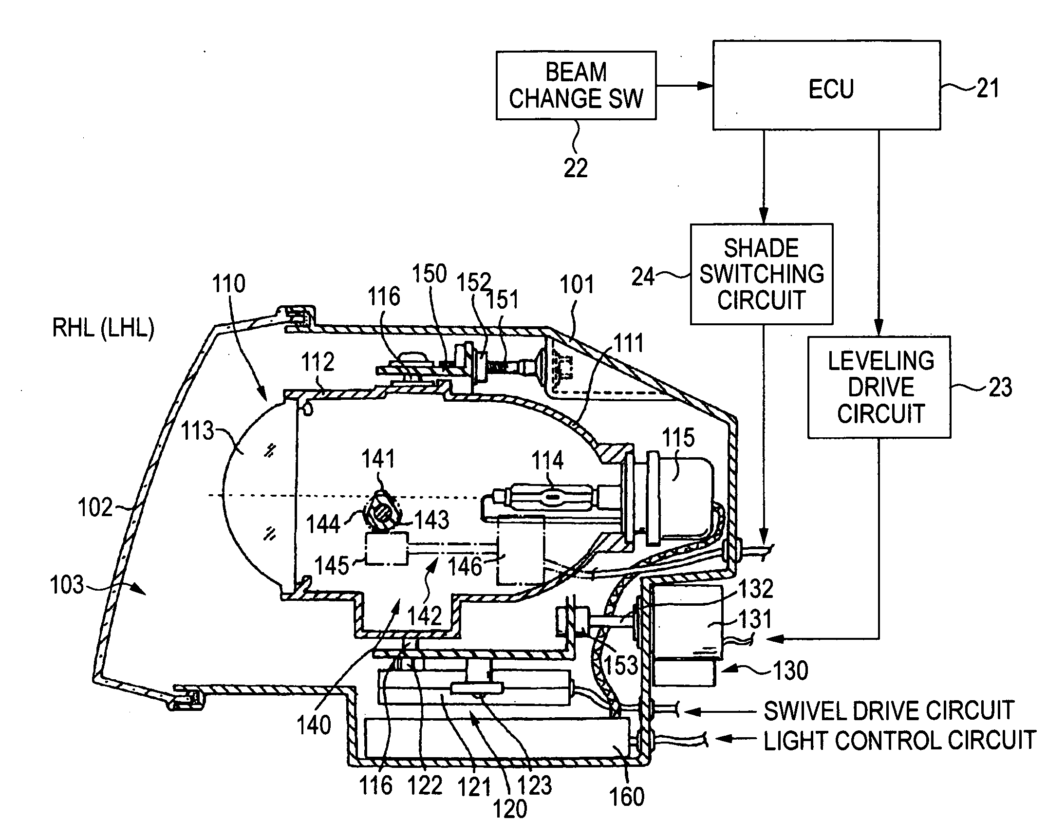
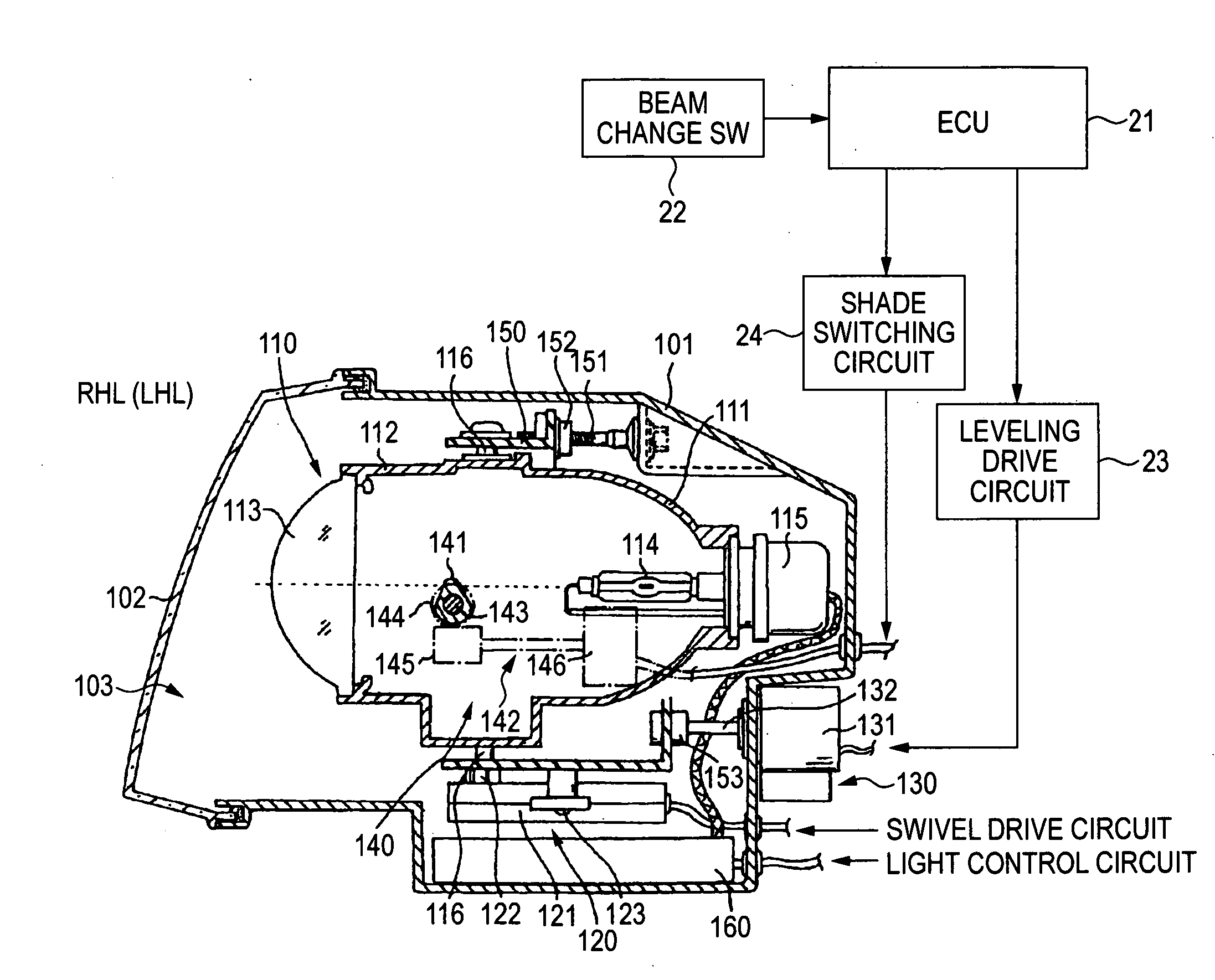
[0024]Embodiment 1 of the invention will be explained in reference to the drawings. FIG. 1 is a sectional view of an embodiment applying the invention to left and right headlamps (headlamps) of an automobile. The drawings show an example of a headlamp capable of deflecting (swiveling) an irradiating direction to left and right sides. The left and right headlamps basically have the same design. The headlamp RHL on the right side is illustrated. The headlamp RHL includes a lamp body 101 formed in a shape of a vessel whose front face is opened. The front face opening is attached with a transparent cover 102 to form a lamp chamber 103. A projector-type lamp unit 110 is mounted inside the lamp chamber 103. The lamp unit 110 is designed to be able to control deflection of an irradiating direction respectively in horizontal left and right directions and vertical up and down directions by a swiveling mechanism 120 and a leveling mechanism 130. A shade for forming a light distribution patter...

embodiment 2

[0037]Embodiment 2 is a headlamp enabling switching of a beam to three different modes of middle beams (“high-middle beam,”“low-middle beam” and “right-middle beam”) in addition to “low beam”“high and beam” as in Embodiment 1. The design of the headlamp is similar to that of Embodiment 1, except the shape of a rotary shade. As shown by a sectional view in FIG. 7, the rotary shade 141A is partitioned into four portions in a circumferential direction, and respective first and second portions form the low beam shade LS having the radius r1 and the high beam shade HS having the radius r2 similar to Embodiment 1. A third portion forms a middle beam shade MS having a length of a radius r3 slightly shorter than that of the low beam shade LS and longer than that of the high beam shade HS. The middle beam shade MS differs from the high beam shade HS and the low beam shade LS in a shape of the shade. That is, a relationship of lengths of radii of the shade in left and right regions interposin...

embodiment 3

[0042]FIG. 9 is a sectional view of a shade provided for a lamp unit of Embodiment 3, where the shade is formed as a straight advancing shade. A guide 147 formed by a shape of a rectangular cylinder is erected to be directed to an upper side from an inner bottom face of the holder 112 of the lamp unit 110, and a support shaft 148 is inserted into the guide hole 147 slidably in an up and down direction. An upper portion of the support shaft 148 is integrally provided with a straight advancing shade 141B constituted by a necessary shape. A portion of a side face of the support shaft 148 is made to face an opening groove 147a provided on one side of the guide 147 and a portion thereof is formed with a rack 148a along the up and down direction. A pinion 149 is arranged inside the holder 112 of the lamp unit 120 and is brought in mesh with the rack 148a. A rotating shaft 149a of the pinion 149 is projected outside by penetrating the one side of the holder 112 similar to the rotating shaf...


PUM


Abstract

A vehicle headlamp includes a lamp 110 having shade switching means 140 for providing a desired light distribution pattern by blocking a portion of light emitted from a light source. Light distribution pattern switching controlling means controls the shade switching means 140 in response to receipt of an instruction of switching a light distribution pattern of the lamp. Leveling means 130 controls deflection of an optical axis of the lamp in a vertical direction. The light distribution pattern switching controlling means controls the shade switching means 140 such that a cut line is formed by a height substantially the same as that of a cut line of high beam when an instruction of switching to a light distribution pattern of “remote optically recognizing beam” is received and controls the leveling means 130 such that the cut line is formed by a height of a cut line requested for “middle beam”.

Description

[0001]This application claims the benefit of priority of Japanese Patent Application No. 2006-041171, filed on Feb. 17, 2006. The disclosure of the priority application is incorporated by reference herein.BACKGROUND OF THE INVENTION[0002]1. Field of the Invention[0003]The present disclosure relates to a headlamp of a vehicle such as an automobile or the like and, in particular, it relates to a vehicle headlamp capable of being switched to multiple different light distribution patterns.[0004]2. Related Art[0005]A headlamp of an automobile or the like is designed to be able to switch a light distribution pattern in accordance with a traveling state and is generally designed to be able to be switched to “low beam” and a “high beam.” The “low beam” (also referred to as “passing beam”) preferably constitutes a light distribution pattern which does not distract the driver of a vehicle traveling in an opposite lane or a vehicle traveling ahead in the same direction. The “high beam” (also r...

Claims


Application Information

Patent Timeline
Patent Type & Authority Applications(United States)
IPC IPC(8): F21V1/00F21Y101/00
CPCB60Q1/0094B60Q1/076F21S48/1794F21S48/145B60Q2300/112F21S41/43F21S41/698
Inventor SUGIMOTO, ATSUSHIMOCHIZUKI, KIYOTAKATATARA, NAOHISA
Owner KOITO MFG CO LTD
Why Eureka
Try Eureka