
Image capturing apparatus

Inactive Publication Date: 2007-08-23
CANON KK
View PDF2 Cites 9 Cited by
  • Summary
  • Abstract
  • Description
  • Claims
  • Application Information

AI Technical Summary

Benefits of technology

[0011]It is an object of the present invention to provide an image capturing apparatus capable of setting a center point of a correction unit, which allows optimal image visibility and image blurring correction irrespective of the zoom state.

Problems solved by technology

A noticeably high rate of decrease in the light amount at the periphery can be caused by a mechanical error or play of a lens barrel which houses lenses, resulting in an increase in variation in the luminances at the four corners (see FIG. 3B).
Especially, the zoom position on the telephoto side suffers a noticeably large change in angle of view.
This results in image data with an angle of view which is not intended by a photographer (with an error of the angle of view at the time of zoom driving), depending on the zoom position.
Furthermore, the visibility of a live image at the time of zoom driving suffers.
However, optimal image blurring correction control sometimes fails when the center point of a shift lens serves as the luminance center in the entire zoom area.

Method used


Image

  • Image capturing apparatus
  • Image capturing apparatus
  • Image capturing apparatus

Examples


Embodiment Construction

[0023]The best mode for carrying out the present invention will be described below.

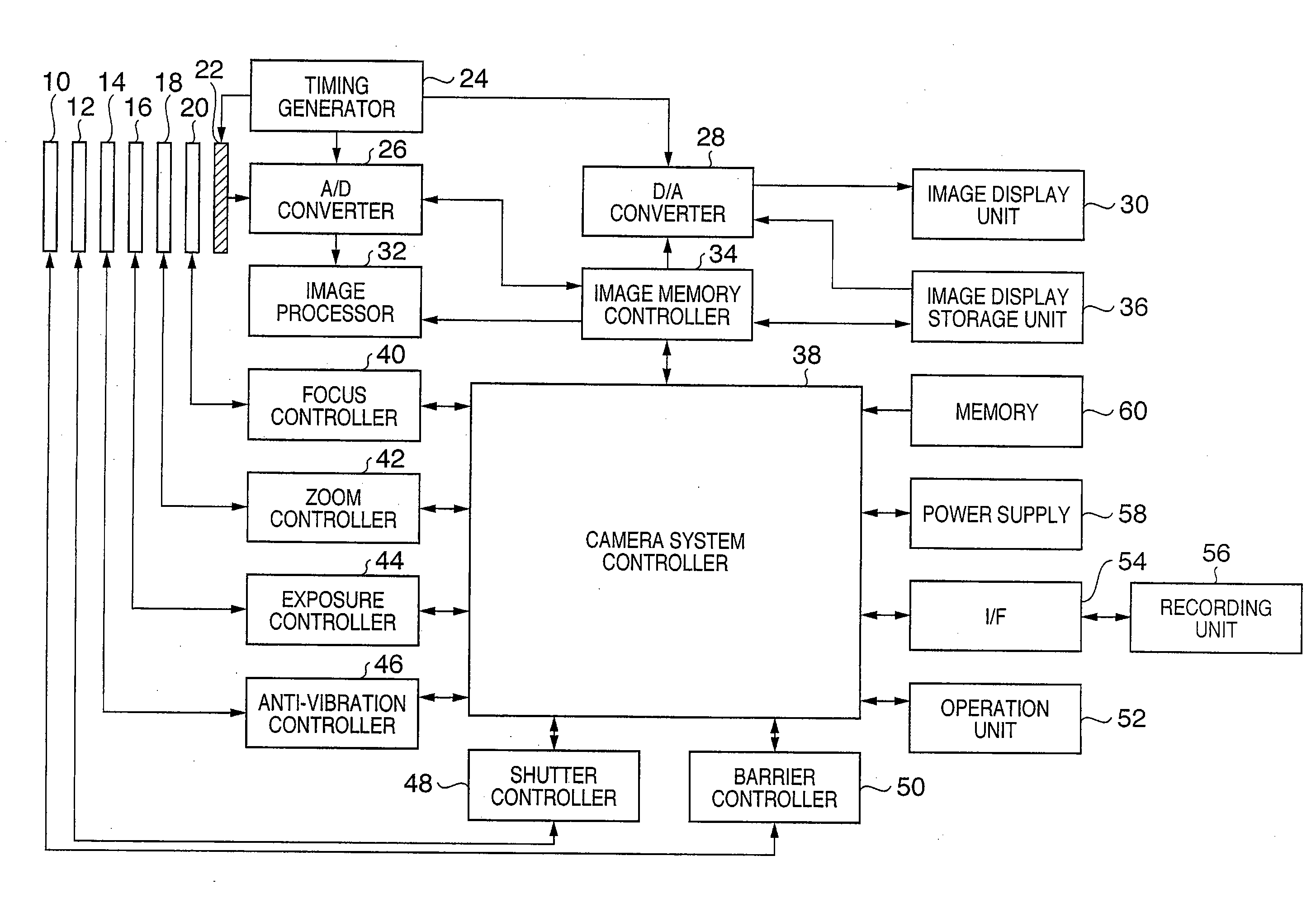
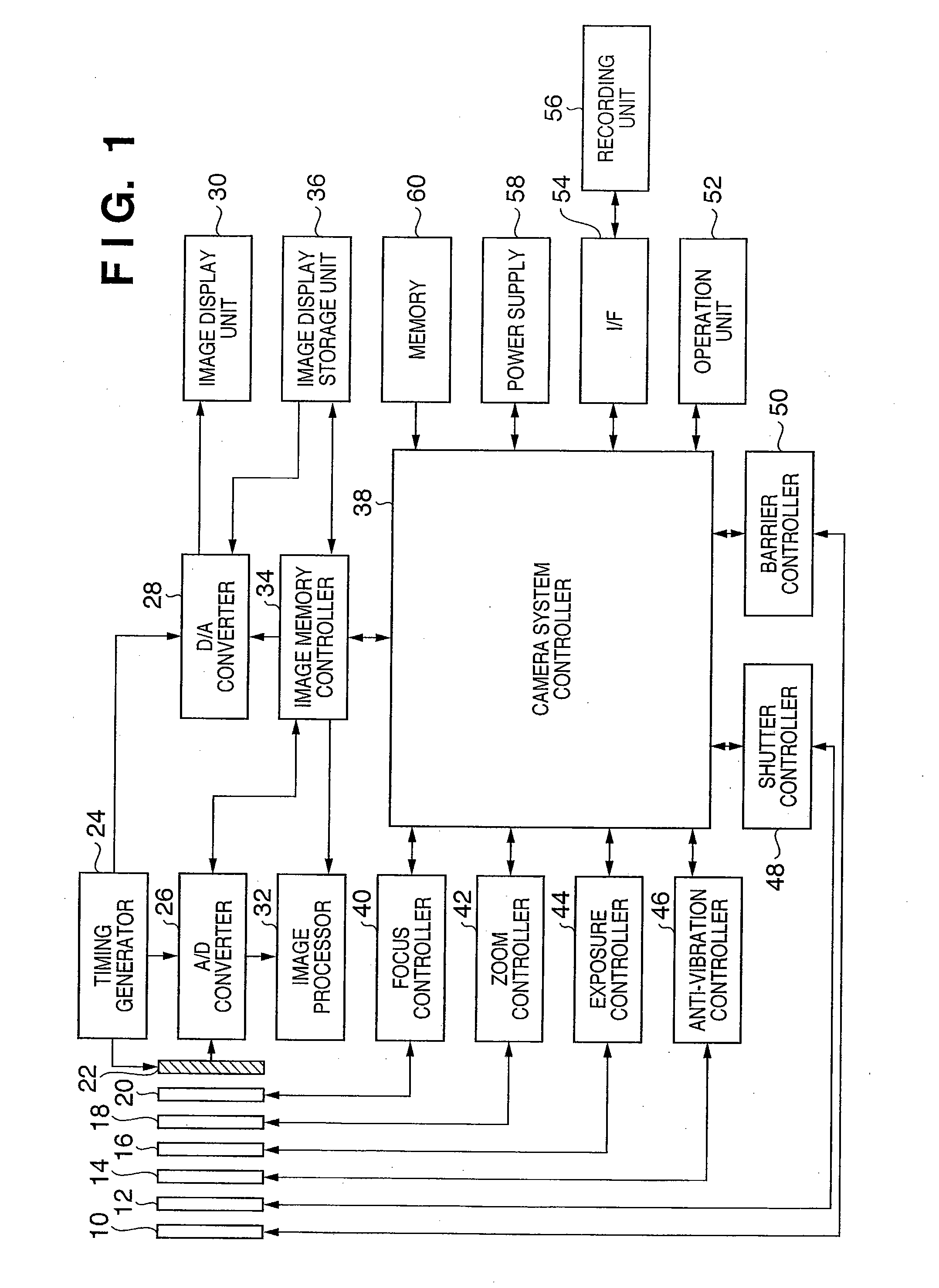
[0024]FIG. 1 is a block diagram showing the circuit arrangement of an image capturing apparatus according to an embodiment of the present invention. Referring to FIG. 1, reference numeral 10 denotes a barrier serving as a photographing lens protection means; 50, a barrier controller for controlling the operation of the barrier 10; 12, a shutter; 48, a shutter controller for controlling the opening / closing of the shutter 12; 14, a shift lens for eliminating image blurring from an image formed on the image sensor 22 (to be described later); 46, an anti-vibration controller for controlling the driving of the shift lens 14; 16, an aperture stop; 44, an exposure controller for controlling the stop 16; 18, zoom lens; 42, a zoom controller for controlling the zoom lens 18 to change the zoom magnification; 20, a focus lens; 40, a focus controller for controlling the focus lens 20 to perform focusing; and 22; ...


PUM


Abstract

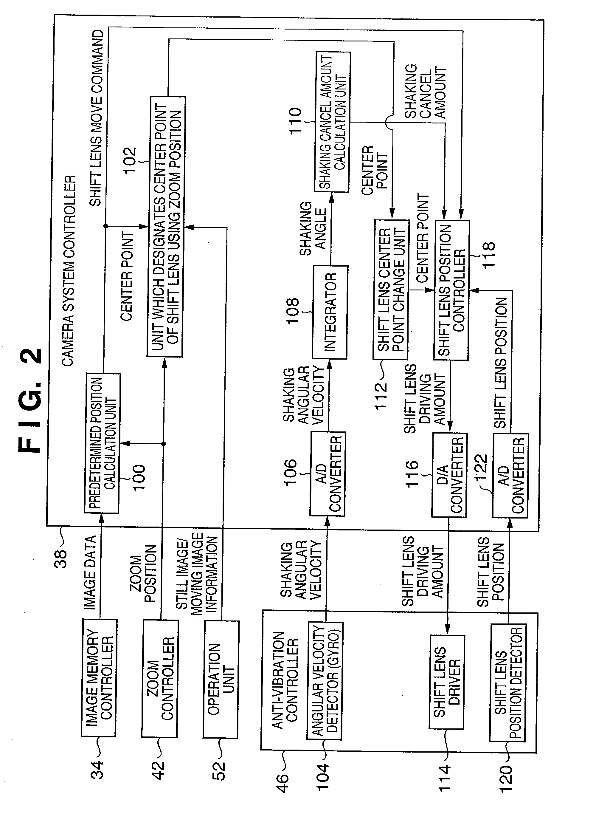
An image capturing apparatus includes a calculation unit which converts shaking detected by a sensor unit into a shaking cancel amount, a correction / driving unit which drives a correction unit using the shaking cancel amount in a plane perpendicular to the optical axis, and corrects blurring of an image formed on an image capturing unit, a zoom position detection unit which detects the current zoom position of a zoom lens, and a center point change unit which changes a center point serving as a movable center of the correction unit in accordance with the zoom position set at either end of the zoom range, or an arbitrary position therebetween. This enables a position of a correction unit to be set which allows optimal image visibility and image blurring correction irrespective of the zoom state.

Description

BACKGROUND OF THE INVENTION[0001]1. Field of the Invention[0002]The present invention relates to an improvement in an image capturing apparatus having an image blurring correction function and zoom position change function.[0003]2. Description of the Related Art[0004]Generally, an image capturing apparatus obtains image data with a periphery including the four corners which is darker than the center of an image. Especially, a phenomenon in which the light amount at the periphery becomes lower than that of the center is called shading. As the rate of decrease in light amount from the center to the periphery increases, or as the four corners form more asymmetric shading, i.e., a variation in their luminances increases, the quality of image data degrades. A lens exhibits a unique degree of decrease in light amount. This property causes a variation in luminance. The degree of decrease in light amount changes also depending on the focal length, i.e., zoom position if the lens is a zoom l...

Claims


Application Information

Patent Timeline
IPC IPC(8): G03B17/00G03B5/00G03B7/28G03B7/30H04N5/232
CPCH04N5/232H04N23/687
Inventor SHIBATA, NOBUHIRO
Owner CANON KK
Learn More