
Method, system, and computer program product for performing prognosis and asset management services

a technology of asset management and prognosis, applied in the field of prognostics, can solve problems such as loss of function, material liberation, and inability to identify fault initiation, and achieve the effect of reducing the number of errors

Active Publication Date: 2007-08-23
GENERAL ELECTRIC CO
View PDF3 Cites 72 Cited by
  • Summary
  • Abstract
  • Description
  • Claims
  • Application Information

AI Technical Summary

Problems solved by technology

During operation, initially localized spall may grow and ultimately result in loss of function.
Subsurface fatigue cracks are induced at locations of peak shear stress, become surface-connected, and lead to eventual liberation of material.
However, in practice this is nearly never the case: features reflect the noise inherent in sensed data and react differently during particular stages of damage evolution (e.g., some are useful for fault detection, but not for damage growth tracking).
However, they may be not as suitable to identification of fault initiation because their resolution is too low for detection of small damage levels.
In addition, absolute counts can be misleading when material gets trapped over time and due to external contamination.
However, the vibration sensor's capacity for early detection comes at the price of sensitivity to environmental effects that are sometimes difficult to quantify or correct.
If diagnostics recognizes the start point of damage too late, the damage propagation models will always lag reality and keep underestimating the damage.
When spall length surpasses a critical value, damage accumulates rapidly; bearing cage failure occurs soon after this threshold has been exceeded.
That is, if an estimate has very large confidence bounds, the utility of such an estimate becomes very small because an operator would have to make decisions to repair components at an otherwise acceptable level of risk.
Deviation in any of those parameters will likely result in an error that is amplified over time.

Method used


Image

  • Method, system, and computer program product for performing prognosis and asset management services
  • Method, system, and computer program product for performing prognosis and asset management services
  • Method, system, and computer program product for performing prognosis and asset management services

Examples


Embodiment Construction

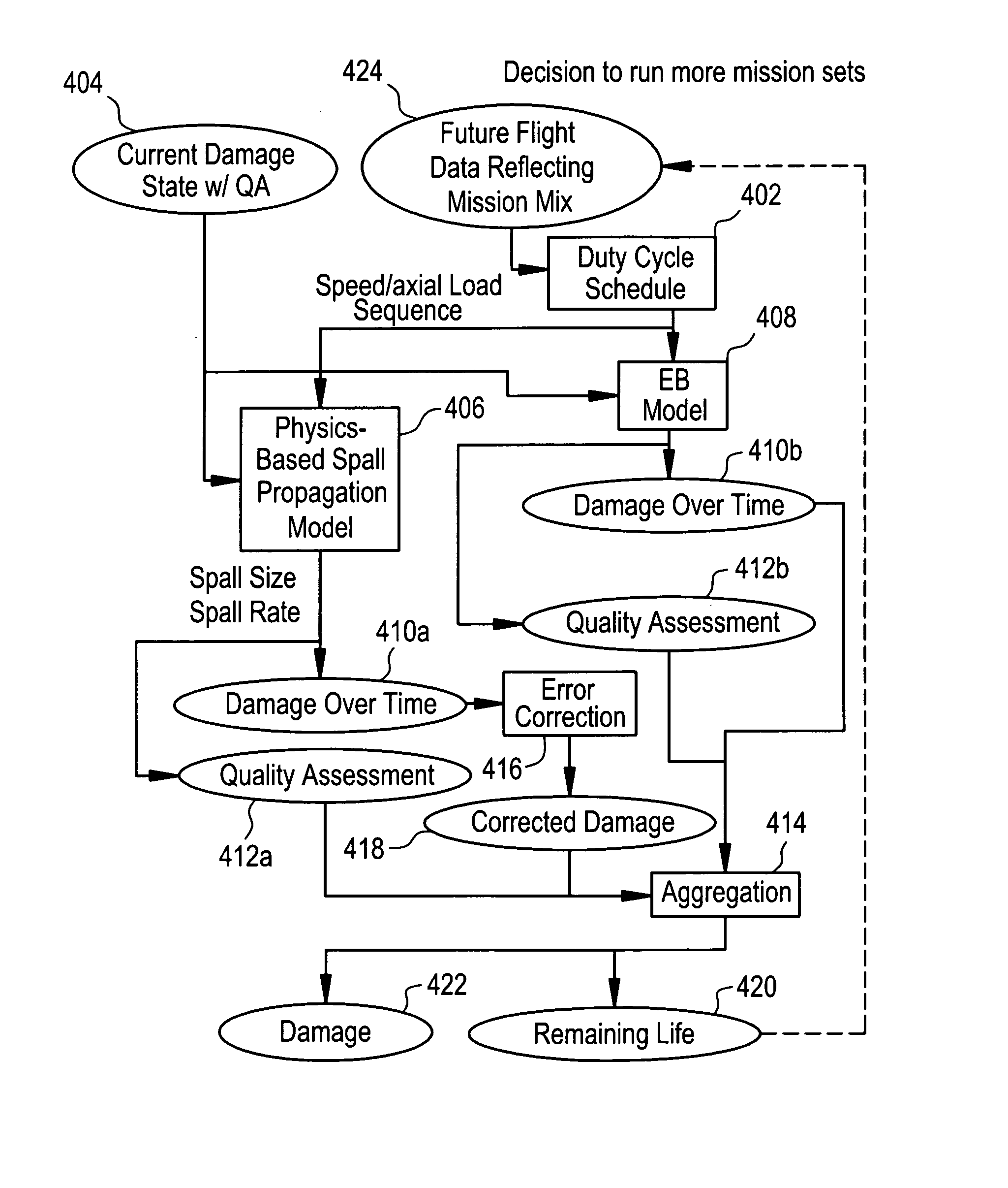
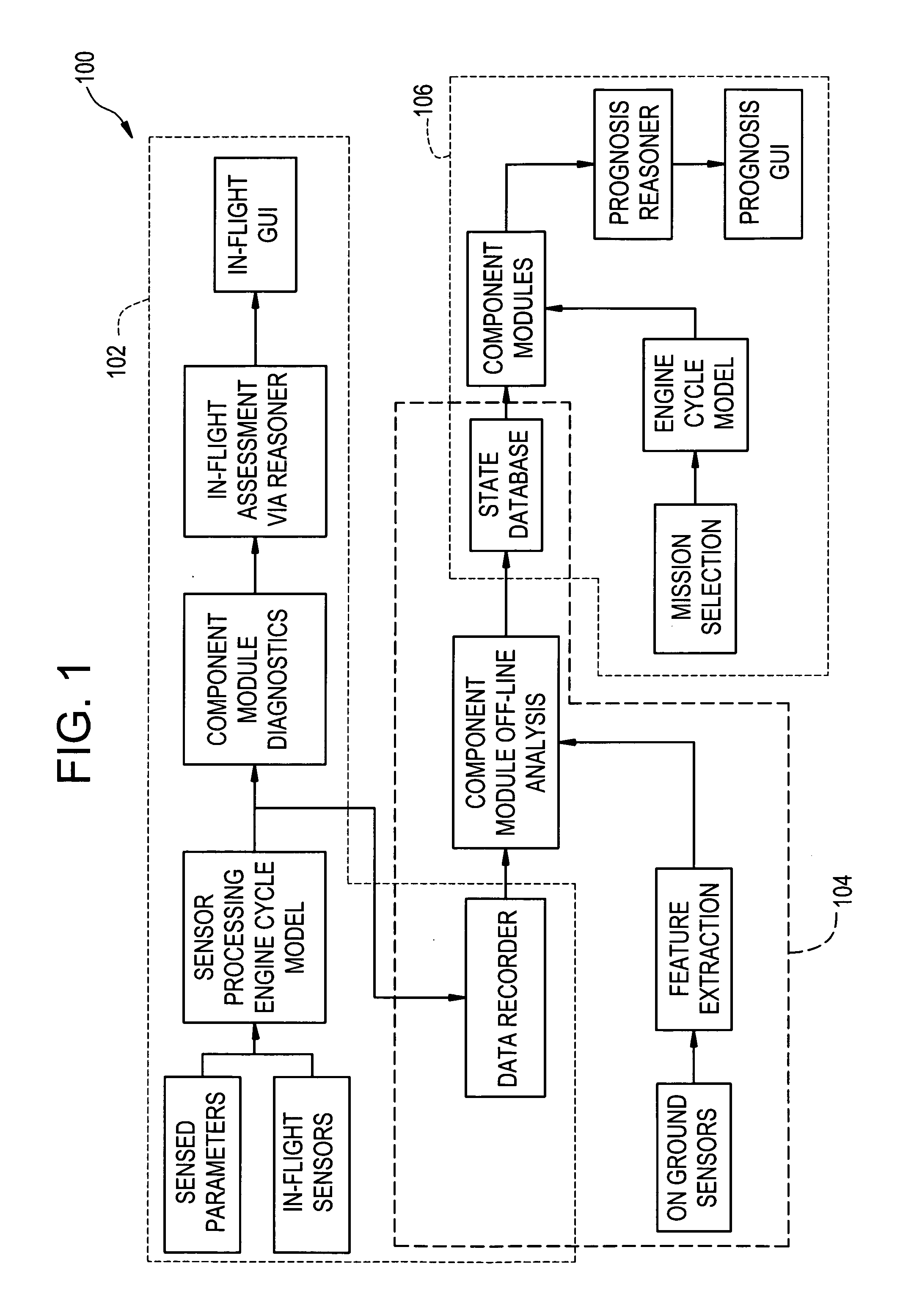
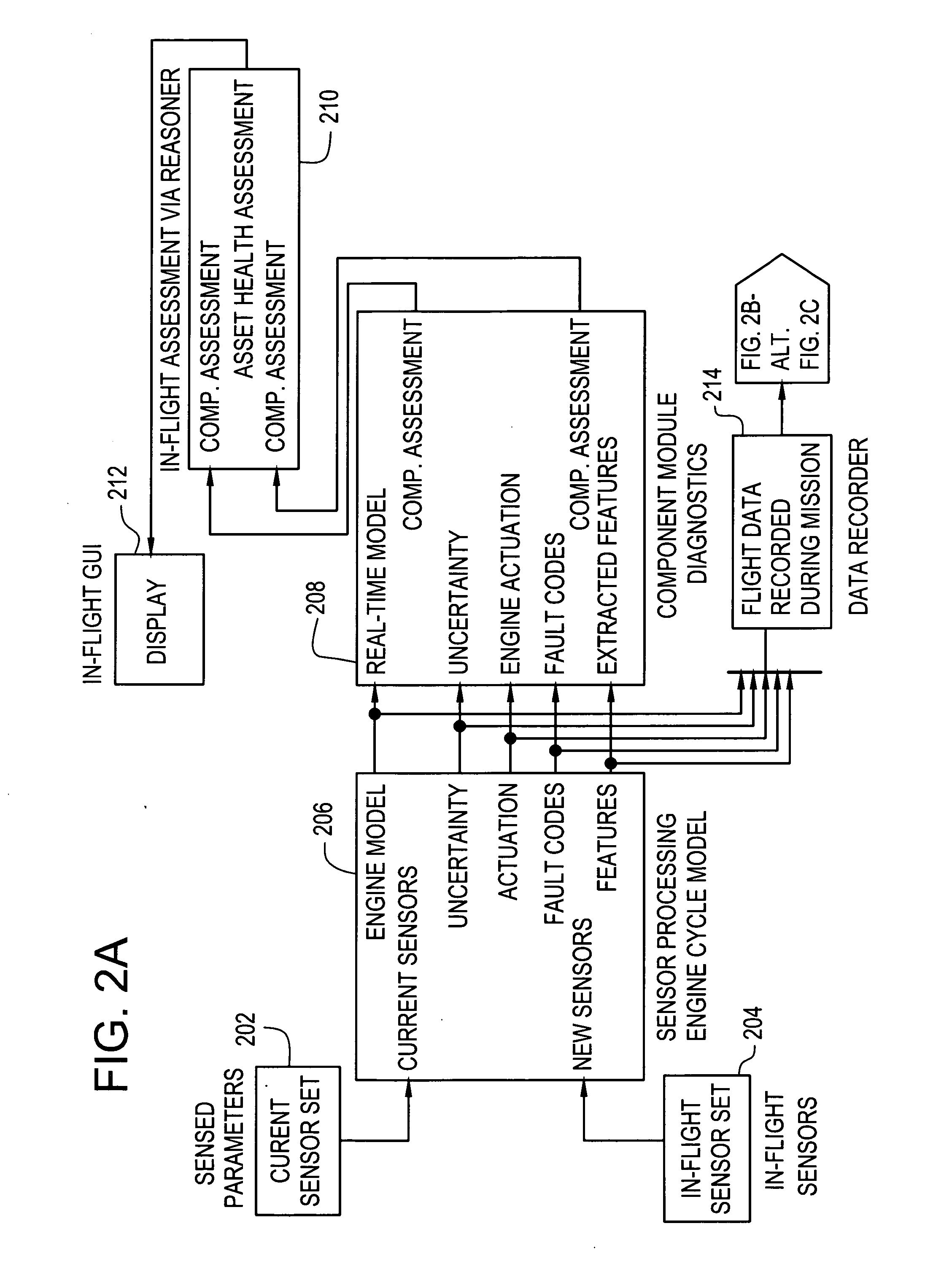
[0036] Turning to FIG. 1, a system architecture 100 for performing prognosis and asset management services including system monitoring, diagnostics, and prognostics for managing system health of an engine (e.g., aircraft engine) will now be described. System 100 includes three subsystems 102-106 as shown in FIG. 1, and are collectively referred to as an integrated prognosis system. Subsystem 102 performs in-flight diagnostics. Subsystem 102 generates component diagnostics and material state assessments in real-time and during flight, using available online sensor data. Subsystem 104 performs post-flight analysis using, in part, information resulting from in-flight diagnostics performed by subsystem 102, as well as other sources. The post-flight analysis activities of subsystem 104 enable more accurate estimates of remaining life of components, and reduce the variance of these estimates. This may be accomplished by including data from additional sources, e.g., ground based inspection...


PUM


Abstract

A method, system, and computer program product for performing prognosis and asset management services is provided. The method includes calculating an accumulated damage estimate for a component via a diagnostics function and applying future mission data for the component to at least one model that calculates accumulated damage or remaining life of the component. The method also includes inputting the accumulated damage estimate to the model and aggregating damage over time and quality assessments produced by the model. The method further includes calculating a damage propagation profile and remaining life estimate for the component based on the aggregating and providing an uncertainty estimate for the damage estimate and the remaining life estimate.

Description

STATEMENT REGARDING FEDERALLY SPONSORED RESEARCH AND DEVELOPMENT [0001] The U.S. Government may have certain rights in this invention pursuant to contract number HR0011-04-C-0002 awarded by the Defense Advanced Research Projects Agency (DARPA) of the Department of Defense (DoD).FIELD OF INVENTION [0002] The present disclosure relates generally to the field of prognostics, and more particularly, to a method, system, and computer program product for providing prognosis and asset management services including system monitoring, diagnostics, and prognostics. BACKGROUND [0003] The field of prognostics, as applied to the operation of complex equipment, relates to a process for estimating the remaining life of a component. Remaining life estimates provide indispensable information for the operation of this equipment. They also provide decision-making aids that allow operators to change operational characteristics (e.g., load) which, in turn, may prolong the life of the component. In additi...

Claims


Application Information

Patent Timeline
Patent Type & Authority Applications(United States)
IPC IPC(8): G06F19/00G01M13/00
CPCG05B23/0283G05B23/0251G01R31/00G05B23/00G06F11/30
Inventor BONANNI, PIERINO GIANNIGOEBEL, KAI FRANKEKLUND, NEIL HOLGER WHITEMOSCARINO, GARY PAUL
Owner GENERAL ELECTRIC CO
Learn More