Living hinge

a technology of living hinges and hinges, which is applied in the field of living hinges, can solve the problems of limiting the flexibility of living hinges, multi-part devices, and high cost of common articulating hinges, and achieves the effects of high cycle-life durability, high flexibility, and simple structur

Inactive Publication Date: 2007-08-30
MC CLELLAN W THOMAS
View PDF41 Cites 40 Cited by
  • Summary
  • Abstract
  • Description
  • Claims
  • Application Information

AI Technical Summary

Benefits of technology

[0009] It is accordingly an object of the invention to provide a living hinge, which overcomes the hereinafore-mentioned disadvantages of the heretofore-known devices of this

Problems solved by technology

Common articulating hinges are relatively complex, expensive, multipart devices with separate parts for rotating attachment edges about a pivot or axis.
However, those same properties of strength and rigidity limit their flexibility to be used as living hinges.
Both the Kulkaski and Smith devices have extremely complicated, mul

Method used


Image

  • Living hinge
  • Living hinge
  • Living hinge

Examples


first embodiment

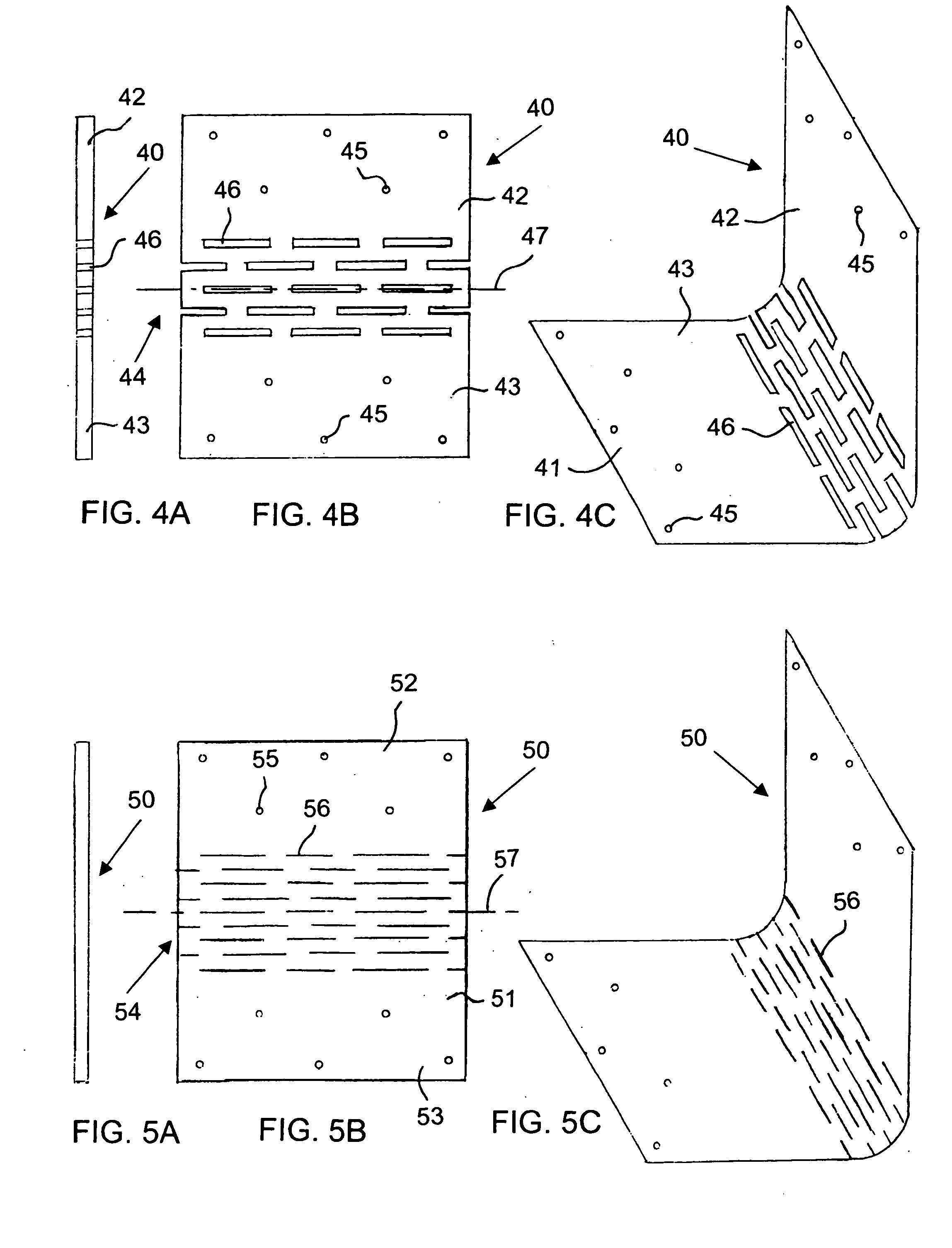
[0030] In the invention illustrated in FIGS. 4A, 4B and 4C, a living hinge 40 has attachment edges 42, 43 with attachment holes 45 formed therein. Through cutouts or separations 46 are formed or cut into the material of a hinge body 41 of the living hinge 40 in rows parallel to a hinging or flexing axis 47 at a flexing zone 44. The individual separations 46 of each row are offset relative to the individual separations 46 of adjacent rows. For example, the center of each individual separation 46 of one row may be aligned with a space between the individual separations 46 of the next row.

second embodiment

[0031] A living hinge 50, according to the invention shown in FIGS. 5A, 5B and 5C, has recesses or separations 56 scored, scratched, laser-cut or dug into the surface of the material of a hinge body 51 of the living hinge between two attachment edges 52, 53 having attachment holes 55. The individual separations 56 in a flexing zone 54 are formed or cut in rows parallel to a hinging or flexing axis 57 and are mutually offset.

third embodiment

[0032]FIGS. 6A and 6B show the invention, in which a living hinge 60 has attachment edges 62, 63 with attachment holes 65 formed therein. Recesses or separations 66 are scored, scratched, laser-cut or dug into the surface of the material of a hinge body 61 of the living hinge at an angle relative to a flexing axis 67 in a flexing zone 64. The angle may, for example, be 30 degrees, 45 degrees or any angle less than 90°.

[0033] It is noted that the desired effect may be accomplished with only one scoring or cutout or only one row of scorings or cutouts and that the scorings or cutouts are interchangeable in each of the embodiments of the inventions.

[0034] The angle (relative to the flexing axis), length, width, overlap and pattern of the separations, recesses or scores which are formed or cut within the material of the living hinge itself converts prior art tension and compression elements into improved function, torsion elements. These recesses, scores or separations are formed or cu...


PUM


Abstract

A living hinge includes a hinge body formed of a material. The hinge body has attachment edges and a flexing zone between the attachment edges defining a flexing axis. The material of the hinge body has at least one separation formed therein in the flexing zone. The at least one separation describes an angle with the flexing axis being other than 90°.

Description

BACKGROUND OF THE INVENTION [0001] 1. Field of the Invention [0002] The invention relates to a living hinge. Such hinges are also known as live or flexible hinges in the art. [0003] 2. Description of the Related Art [0004] Common articulating hinges are relatively complex, expensive, multipart devices with separate parts for rotating attachment edges about a pivot or axis. Living or live hinges are relatively simpler, lower-cost, one-piece flexing devices or functional hinges having of a flexing zone between attachment edges. [0005] A living hinge of high strength requires the desirable qualities of toughness and stability found in metal or other high strength materials. However, those same properties of strength and rigidity limit their flexibility to be used as living hinges. [0006] U.S. Pat. No. 6,355,335 to Kulkaski discloses a flexible hinge having a thin flexible web between two inflexible members. U.S. Pat. No. 4,619,304 to Smith teaches a hinged structure having S-shaped hin...

Claims


Application Information

Patent Timeline
IPC IPC(8): E05D7/00
CPCE05D1/02Y10T16/52Y10T16/524Y10T16/525
Inventor MC CLELLAN, W. THOMAS
Owner MC CLELLAN W THOMAS
Why Eureka
Try Eureka