Vacuum Sealer

a vacuum sealer and sealer technology, applied in the field of vacuum sealers, can solve the problems of reducing the durability of the product, not being installed or detached, and affecting the use of weak users, and achieve the effect of simplifying the construction of the vacuum sealer

Inactive Publication Date: 2007-08-30
SUNG YI JE
View PDF11 Cites 30 Cited by
  • Summary
  • Abstract
  • Description
  • Claims
  • Application Information

AI Technical Summary

Benefits of technology

The technical effect of this patent is that it provides a vacuum sealer with a simplified design by having a straight-line shaped packing member located at the bottom of the machine. This makes it easier for users to assemble and operate the device.

Problems solved by technology

The technical problem addressed in this patent is improving the design of vacuum seakers to make them more efficient, cost-effective, and easy to use. Specifically, the current designs require manual labor to operate the vacuum release mechanism, leading to inconvenience and potential leaks due to poor maintenance. Additionally, some designs fail to provide adequate ventilation for certain types of products, while others lack stability and reliability over extended periods of usage. There also exists limitations related to limited storage spaces and difficulty in accessing high-speed power sources.

Method used


Image

  • Vacuum Sealer
  • Vacuum Sealer
  • Vacuum Sealer

Examples


Embodiment Construction

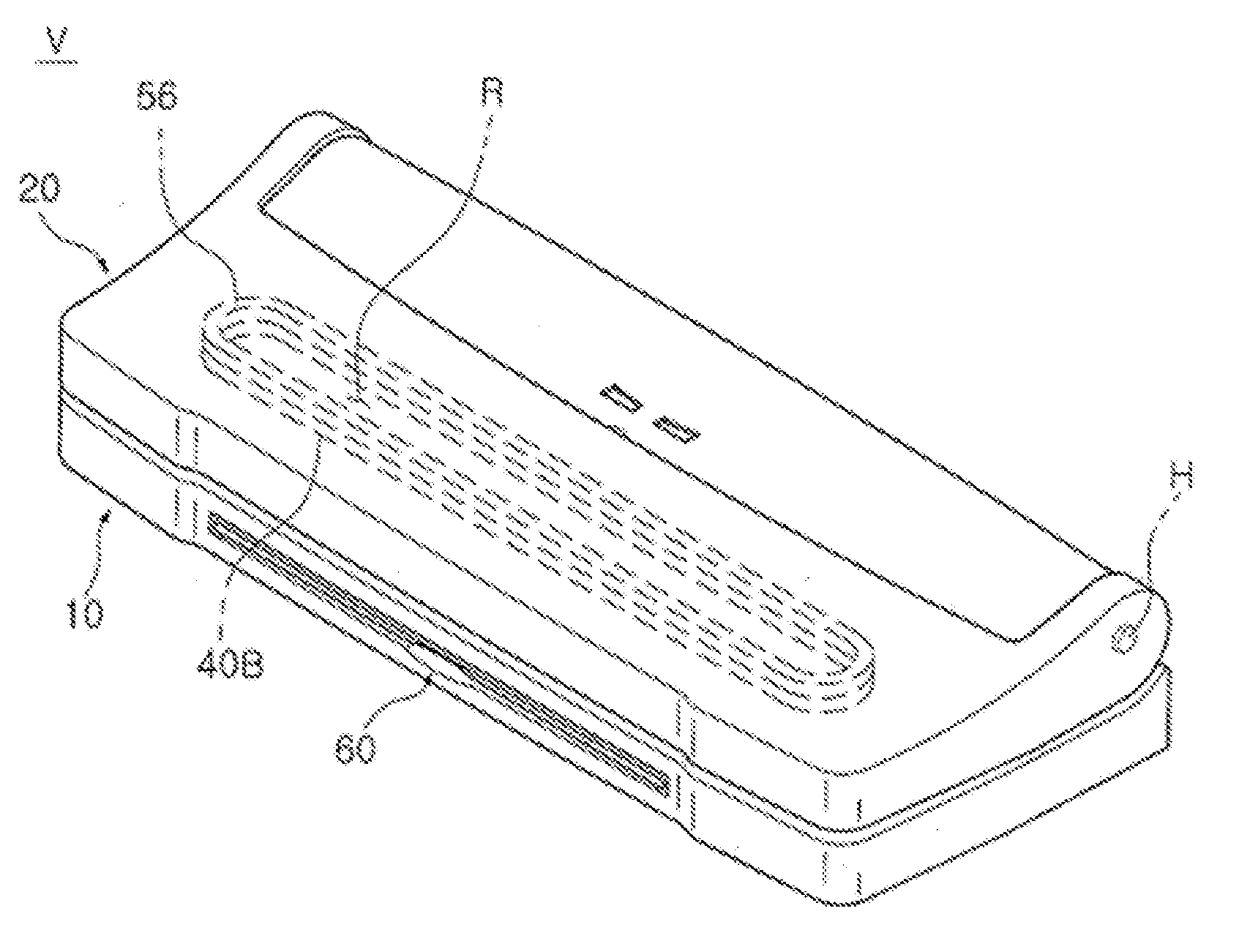
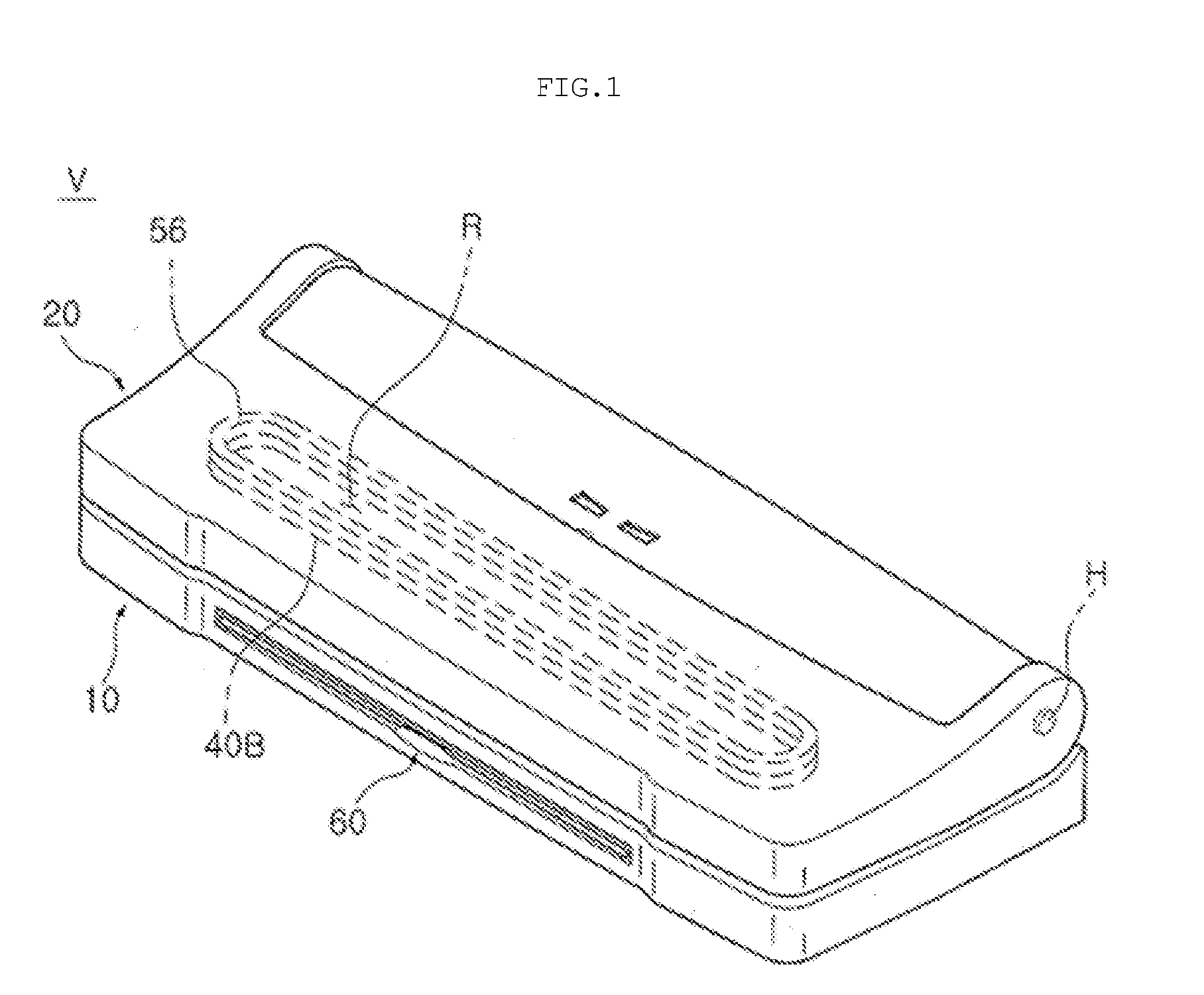
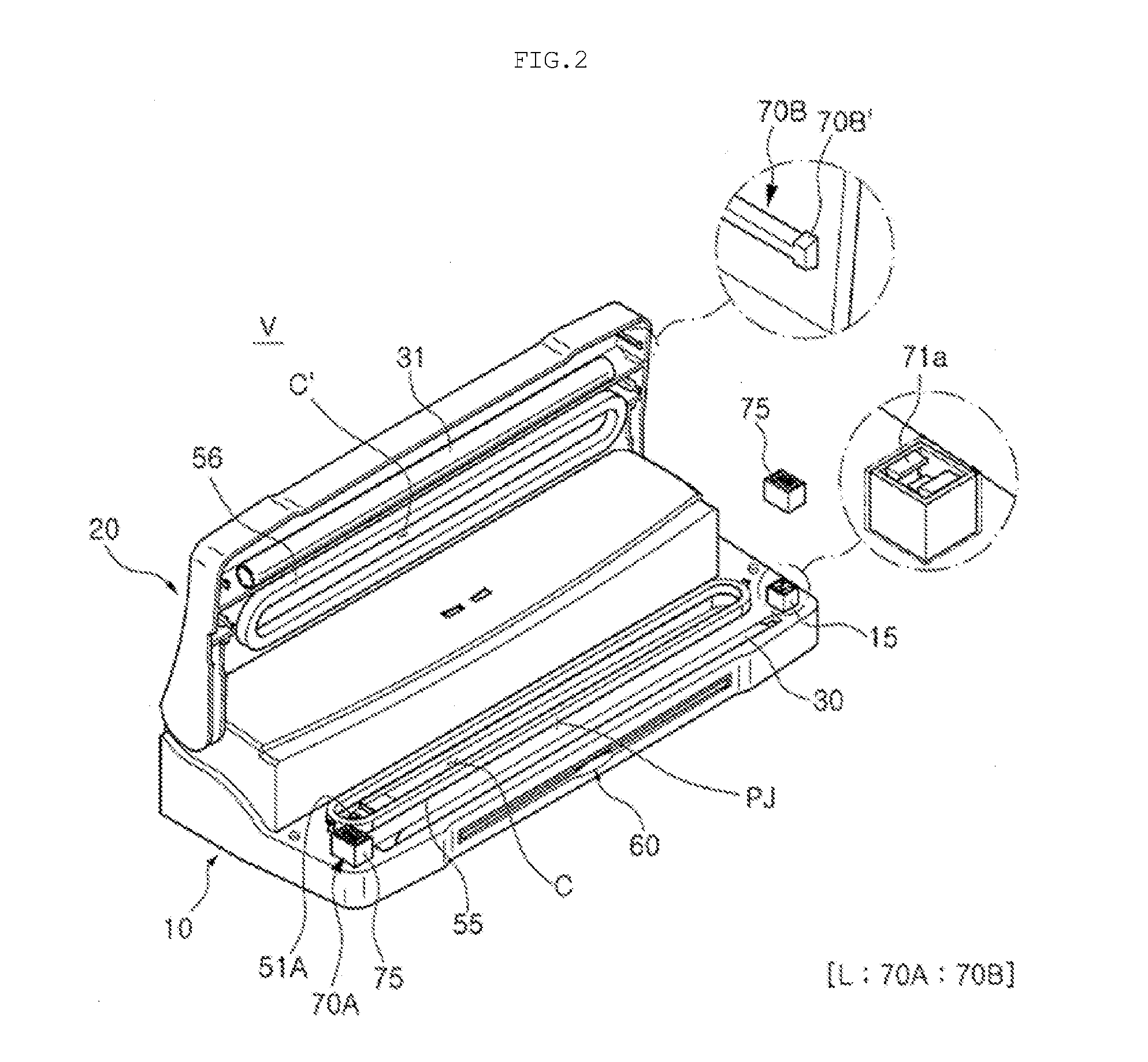
[0047] The present invention will be described below in detail with reference to the accompanying drawings. The same reference numerals throughout the drawings, that is, the same reference numerals in a second digit and a first digit, or in a second digit, a first digit, and an alphabet character, denote elements having the same function. If there is no special mention, the elements denoted by the reference numerals are to be taken as elements complying with the above-mentioned reference scheme. The orientation of the vacuum sealer V according to the present invention is specified with reference to FIGS. 1 and 2. That is, the position of an element 10 which is located at a lower position when seen from the direction in which gravity acts, and holds important parts, such as a heater 30 and a pump 40 (see, FIG. 11) is set as a lower position, and the element 10 is designated as a ‘lower body’. The position opposite the position of the lower body is set as an upper position, and an ele...


PUM


Abstract

Disclosed herein is a vacuum sealer, which exhausts air from a thermal adhesive vacuum bag containing products and then heats and seals the open end of the vacuum bag. The vacuum sealer includes a lower body. An upper body is pivotably mounted to the lower body in such a way as to engage with the lower body. A heater is installed in either or both the lower body or/and the upper body, and heats and seals a vacuum bag. A vacuum space creating member is installed in either or both the lower body or/and the upper body, and isolates an end of the vacuum bag which is evacuated from an exterior, thus creating a vacuum space. A vacuum pump is coupled via a tube to an exhaust hole communicating with the vacuum space created by the vacuum space creating member.

Description


Claims


Application Information

Patent Timeline
Owner SUNG YI JE
Why Eureka
Try Eureka