Vertical tri-color sensor

a tri-color sensor and vertical technology, applied in the field of vertical tri-color sensors, can solve the problems of degrading the image quality, prone to crosstalk between pixels, and color sensor arrays b>20/b>

Inactive Publication Date: 2007-08-30
APTINA IMAGING CORP
View PDF8 Cites 75 Cited by
  • Summary
  • Abstract
  • Description
  • Claims
  • Application Information

AI Technical Summary

Problems solved by technology

However, all of these algorithms introduce demosaicing artifacts into the interpolated color image, which degrade the quality of the image.
However, this stacked structure makes the color sensor array 20 susceptible to crosstalk between the pixels.

Method used


Image

  • Vertical tri-color sensor
  • Vertical tri-color sensor
  • Vertical tri-color sensor

Examples


Embodiment Construction

[0032] Reference will now be made in detail to embodiments in accordance with the invention, examples of which are illustrated in the accompanying drawings, wherein like reference numerals refer to the like elements throughout. The embodiments in accordance with the invention are described below.

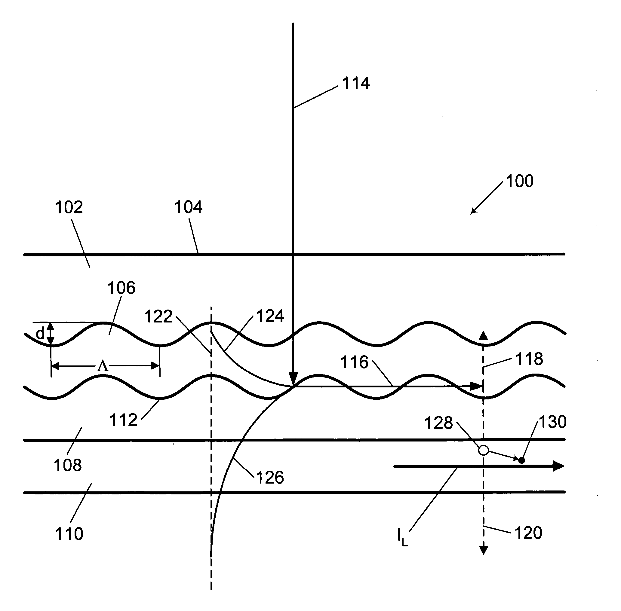
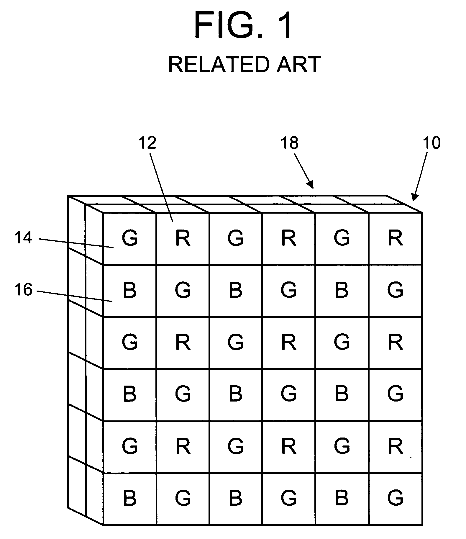
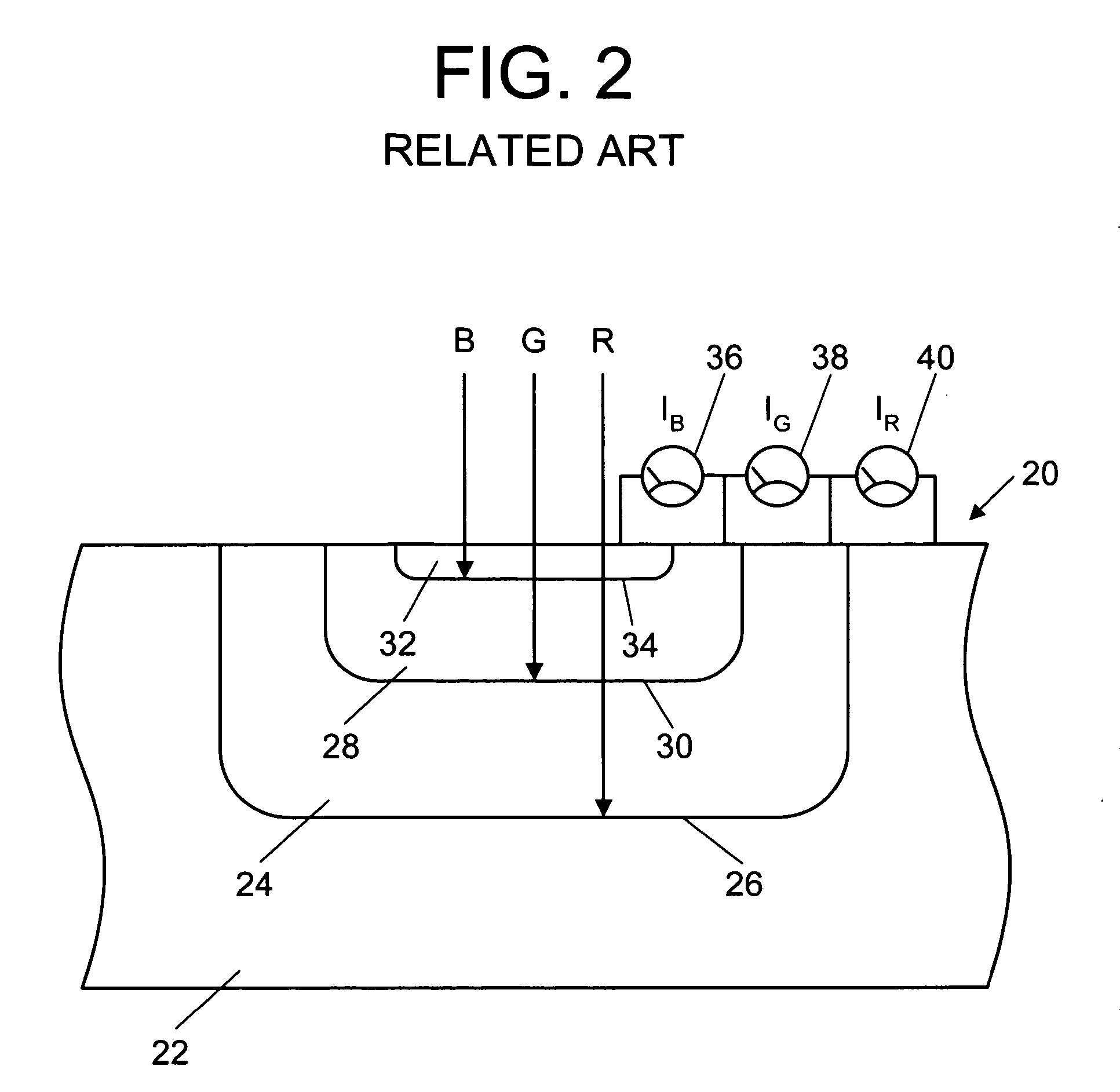
[0033] It occurred to the inventors of this invention that blue, green, and red components of light incident on a silicon substrate can be detected by converting the blue, green, and red components to surface plasmons using three vertically stacked gratings or corrugated surfaces tuned to the frequency of the blue, green, and red components, and that such an arrangement would enable vertically stacked blue, green, and red pixels to be of equal size no larger than one pixel of a monochromatic sensor array, and that there would be reduced crosstalk between the pixels as compared to the color sensor array 20 of the related art shown in FIG. 2.

[0034] A surface plasmon can be thought of as a ve...


PUM


Abstract

A vertical tri-color sensor having vertically stacked blue, green, and red pixels detects at least blue and green components of incident light by converting the blue and green components to surface plasmons.

Description

BACKGROUND OF THE INVENTION [0001] Sensor arrays are used in a wide variety of optical devices. A sensor array contains an array of pixels which are typically responsive to visible light and, to a lesser degree, to infrared light. Thus, a sensor array will produce a monochromatic signal representative of all colors of visible light, with each pixel producing a signal indicative of light incident on that pixel. [0002] Any color, within limits, may represented by a linear combination of three additive primary colors, such as red, green, and blue. To enable a sensor array to sense color, a color filter array having red, green, and blue filter elements is overlaid on the sensor array so that each filter element of the color filter array is aligned with one pixel of the sensor array. [0003]FIG. 1 shows a color sensor array including a color filter array 10 having red elements 12, green elements 14, and blue elements 16 arranged in what is known as a Bayer pattern, which is named after it...

Claims


Application Information

Patent Timeline
Patent Type & Authority Applications(United States)
IPC IPC(8): H04N9/083H04N3/14H04N5/335H04N9/04
CPCB82Y20/00G02B5/008G02B5/201H04N2209/047H01L27/1462H01L27/14647H01L31/111G02B6/1226G02B5/20
Inventor GRUHLKE, RUSSELL W.BURAK, DARIUSZDUNGAN, THOMAS E.
Owner APTINA IMAGING CORP
Why Eureka
Try Eureka