
Hydraulic Drive, in Particular for Two-Cylinder Thick Matter Pumps

Inactive Publication Date: 2007-09-06
PUTZMEISTER AG
View PDF3 Cites 8 Cited by
  • Summary
  • Abstract
  • Description
  • Claims
  • Application Information

AI Technical Summary

Benefits of technology

[0006] Beginning therewith it is the task of the invention to make arrangements which ensure that the low pressure collapse in the h

Problems solved by technology

Due to the mass inertia and the compressibility in the system, substantial pressure oscillations result within the hydraulic system during the reversal process of the reversible pump.
This leads to an extreme discharge of flushing oil from the until now low pressure side of the main circuit so that, in the course of the renewed pressure buildup on the high pressure side, the pressure on the low pressure side can completely c

Method used


Image

  • Hydraulic Drive, in Particular for Two-Cylinder Thick Matter Pumps
  • Hydraulic Drive, in Particular for Two-Cylinder Thick Matter Pumps
  • Hydraulic Drive, in Particular for Two-Cylinder Thick Matter Pumps

Examples


Example

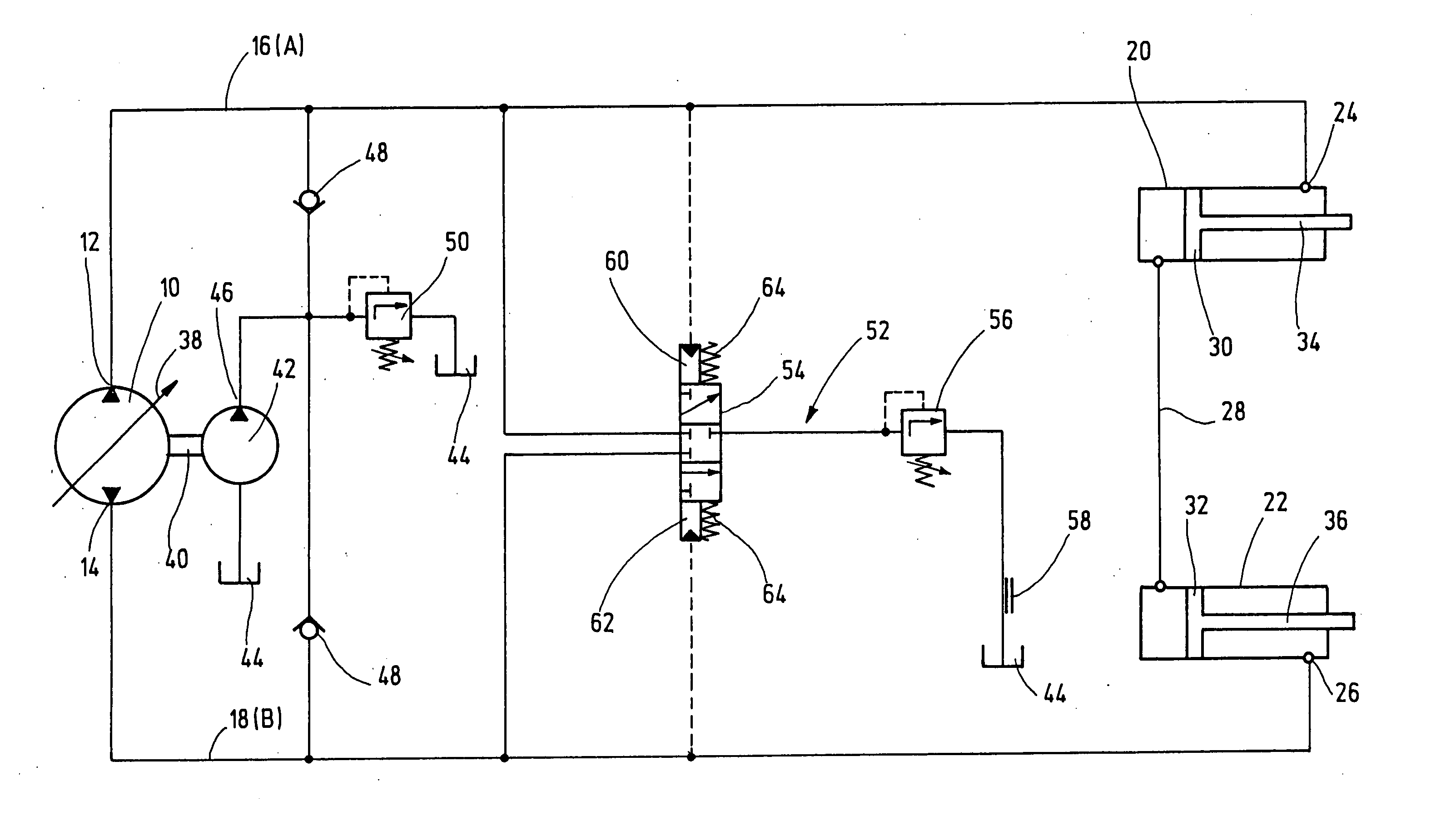
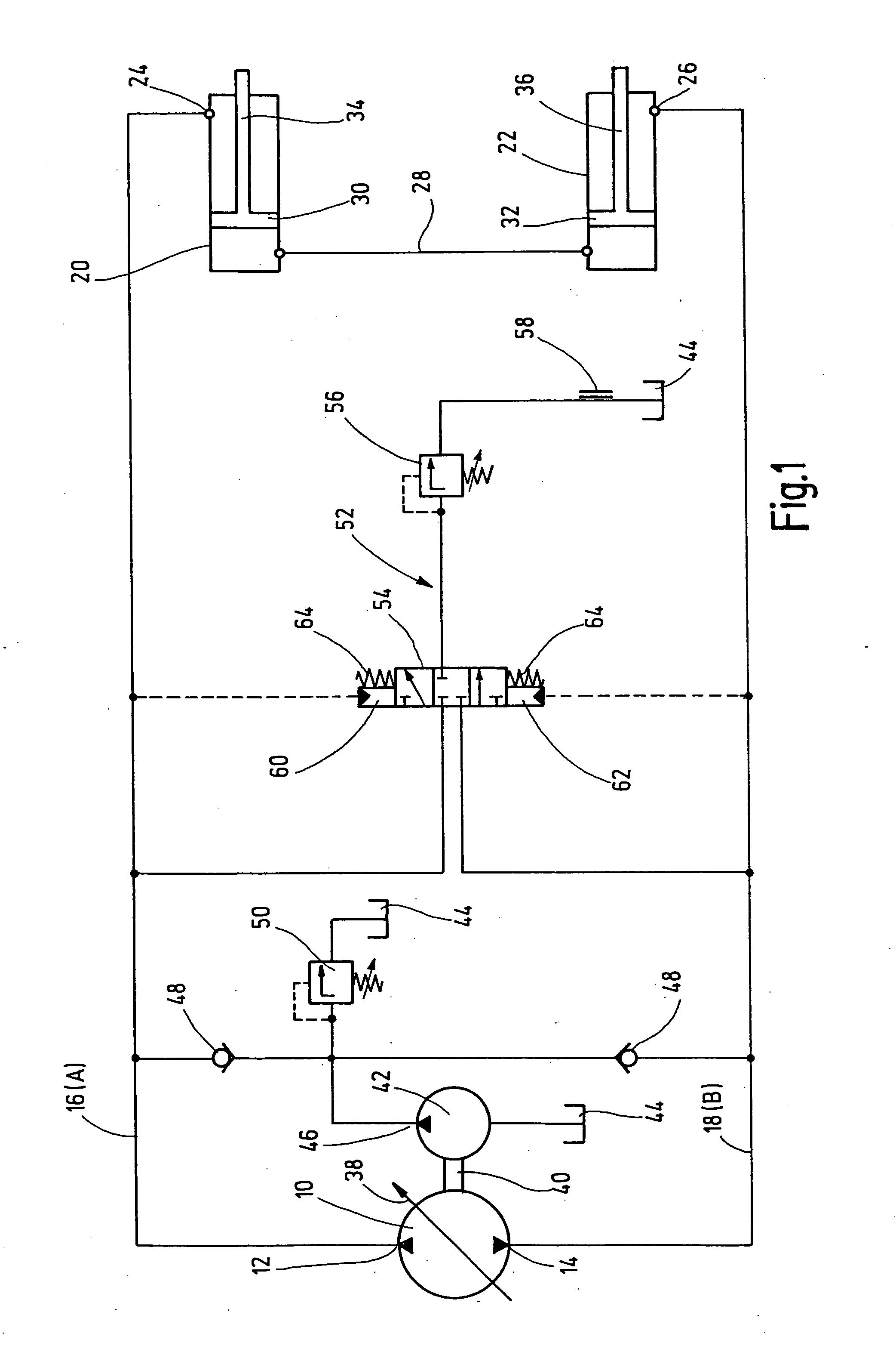
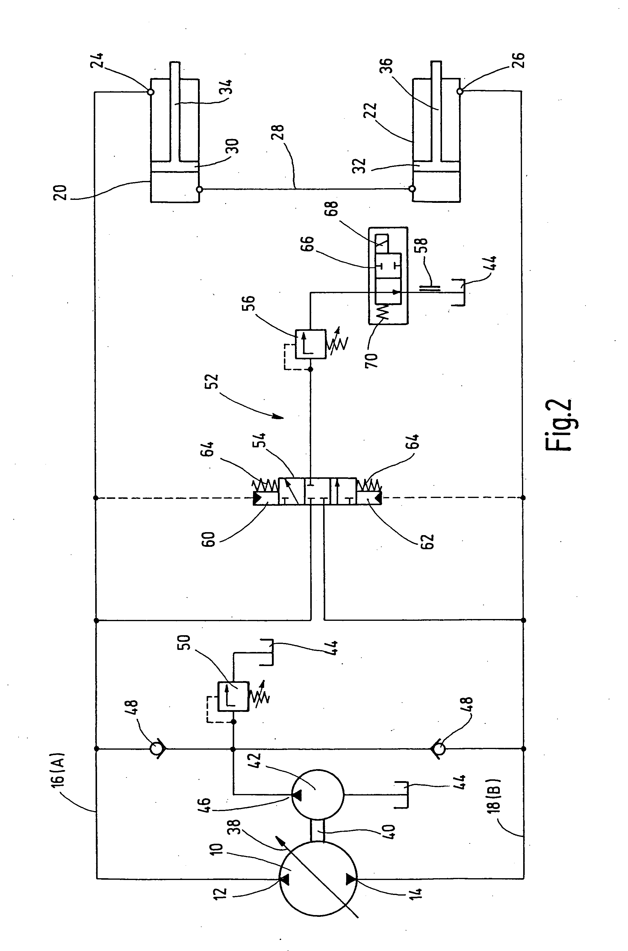
[0020]FIGS. 1 and 5 show the basic circuit diagram for a drive hydraulic for a two-cylinder thick matter pump with a closed hydraulic circuit and a flushing branch.

[0021] The basic circuit includes a hydraulic pump 10 embodied as a reversing or adjustable pump, to the outlets 12, 14 of which piston-cylinder units embodied as drive cylinders 20 and 22 are connected via respectively one connection pipe 16, 18. In the illustrated embodiment the pump connections 24, 26 are respectively located on the rod end of the drive cylinder. On their opposite end the drive cylinders are connected with each other via an oscillating hydraulic line 28. A pistons 30, 32, with the associated piston rods 34, 36 of the drive cylinders 20, 22, are alternatingly driven in counterstroke via the main pump 10. For this, a pivot disk 38 of the pump is so reversed via a not shown hydro-mechanical or electro-mechanical control mechanism within the main pump that the high pressure side and the pre-tensioned low ...


PUM


Abstract

The invention relates to a hydraulic drive, especially for two-cylinder thick matter pumps. Said hydraulic drive comprises at least one main pump ( 10 ) embodied as a hydraulic variable displacement pump, and two hydraulically actuatable drive cylinders ( 20,22 ) that are each connected to a connection line ( 16,18 ) of the main pump ( 10 ) by means of pump connections mounted on one end thereof, forming a closed hydraulic circuit, and communicate with each other at the ends thereof opposing the pump connections ( 24,26 ) by means of a swinging oil line ( 28 ). The hydraulic drive also comprises a feed pump ( 42 ), by which means pressurized oil is fed from an oil tank to the current low-pressure side into the hydraulic circuit, and a flushing branch ( 52 ), by which means a flushing oil flow is branched off from the current low-pressure side under a limited pressure into the oil tank ( 44 ). In order to avoid low-pressure influxes during the reversal process of the main pump ( 10 ), the flushing oil flow is blocked and then released in a time-delayed manner during each reversal process of the main pump ( 10 ), independently of the differential pressure in the connection lines.

Description

CROSS REFERENCE TO RELATED APPLICATION [0001] This application is a national stage of PCT / EP2006 / 001432 filed on Feb. 2, 2006 and based upon Application No. 10 2005 008 2173.3 filed on Feb. 22, 2005 under the International Convention.BACKGROUND OF THE INVENTION [0002] 1. Field of the Invention [0003] The invention concerns a hydraulic drive, in particular for a two-cylinder thick matter pump of the general type described in the pre-characterizing portion of claim 1. [0004] 2. Description of Related Art [0005] Known hydraulic drives of this type include at least one main pump embodied as a hydraulic variable displacement pump as well as two hydraulically actuated drive cylinders embodied as piston cylinder units. The drive cylinders are connected at their one end via pump connections with respectively one of two connection lines of the main pump, forming a closed hydraulic circuit, while on their end opposite to the pump connections they are in communication with each other via an os...

Claims


Application Information

Patent Timeline
IPC IPC(8): F16D31/02
CPCF04B9/1178F04B15/02F15B7/10F16H61/4104F15B2211/613F15B2211/7053F15B2211/7121F15B2211/20561
Inventor VON BAUMEN, PAULHOVEMEYER, DIRKRENZ, HANS
Owner PUTZMEISTER AG
Learn More