Hanging storage system and attachment means

a storage system and hanging technology, applied in the field of storage systems, can solve the problems that state of the art rack systems cannot be connected to the ceiling, and achieve the effect of improving strength and useful attachment ability

Active Publication Date: 2007-09-06
EAGLE IND GRP
View PDF12 Cites 37 Cited by
  • Summary
  • Abstract
  • Description
  • Claims
  • Application Information

AI Technical Summary

Benefits of technology

[0008] The present invention provides a ceiling attachment bracket capable of spanning the required ceiling truss separation, usually 16″ to 24″. This is done with a special angle iron fitted with two connection points. The installation process is made easier and a stronger, and a two-connection-point attachment is made with the truss. This attachment strategy increases the load capacity of the present invention over competing designs.
[0010] Note that in the Mikich patents, the “adapters” provided are very short, and will not account for multiple-beam connection with beams that are a nonstandard distance apart. The present invention provides significantly wider attachment brackets instead of adapters, permitting the installer to find a much more convenient attachment point for placing bolt holes closer to the center of the ceiling truss. For example, the holes on the Mikich adapter are in a single line unlike the present invention's staggered double line, which provides a significantly more useful attachment ability, permitting the installer to pick a drilling point closer to the center of the ceiling truss for maximum security.
[0011] The invention also possesses in an alternate embodiment a three-sided, C-shaped longitudinal beam for the support rack frame, providing substantial strength improvements over the standard two-sided angle iron

Problems solved by technology

Several of the state of the art rack systems can not be connected to a ceiling where rafters were set at nonstandard separations.

Method used


Image

  • Hanging storage system and attachment means
  • Hanging storage system and attachment means
  • Hanging storage system and attachment means

Examples


Embodiment Construction

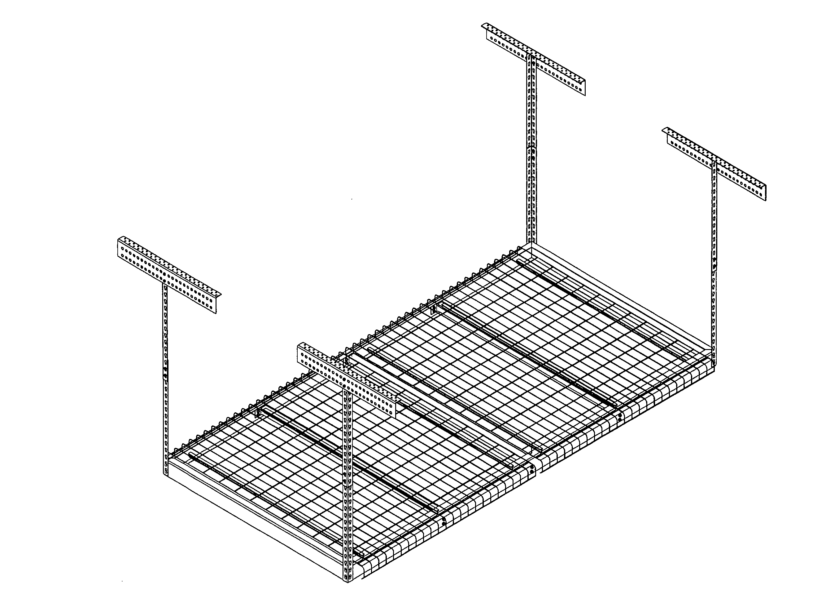
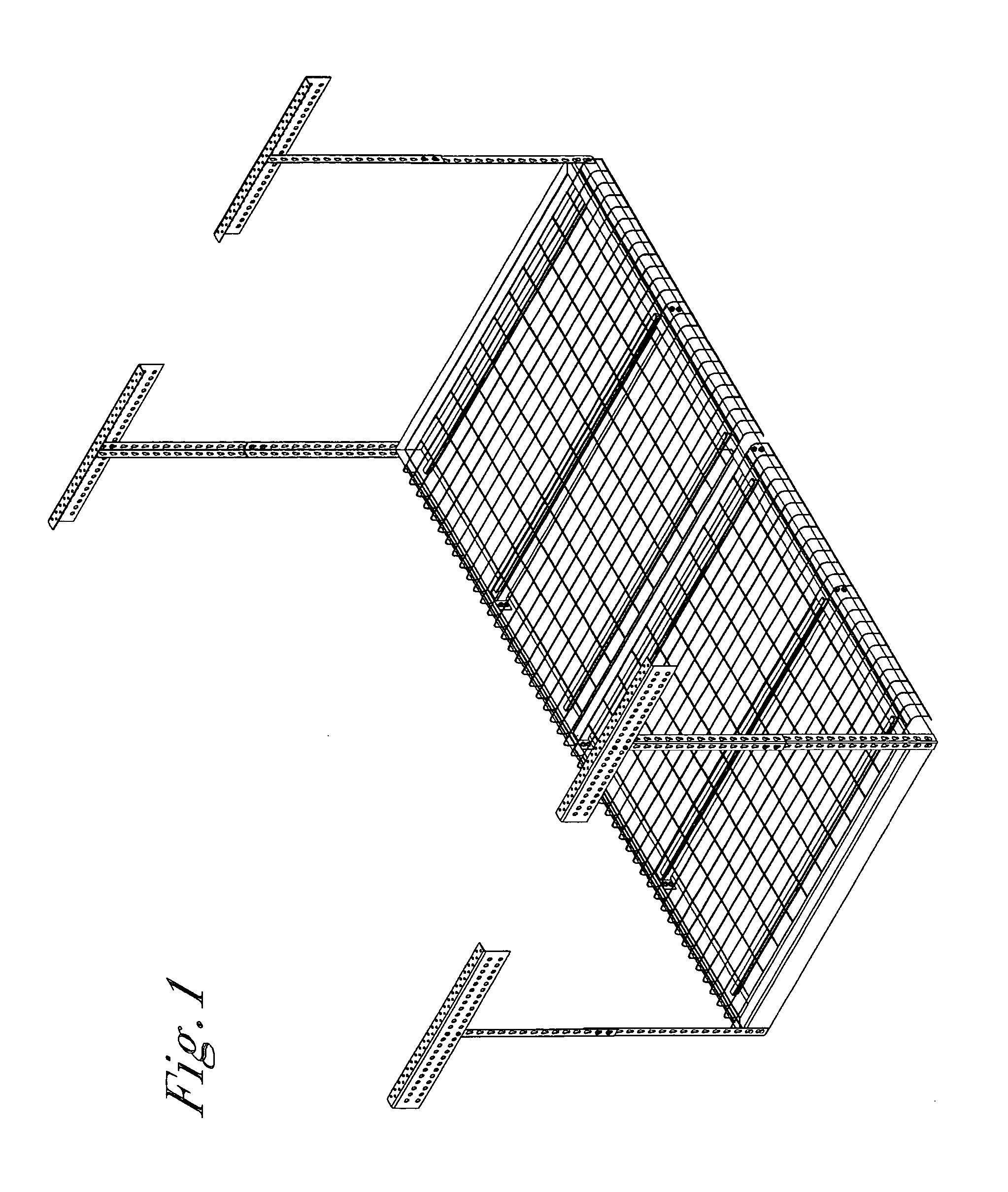
[0020] The present invention is shown in a perspective overview in FIG. 1. The invention 100 consists of the four ceiling attachment brackets 101, four adjustable risers 102 dropping from the attachment brackets 101, a set of cross members 105 and a frame 103, 104, and on top of the assembled frame 103, 104 and cross members 105 a screen of metal mesh 106 to support items carried by the storage system.

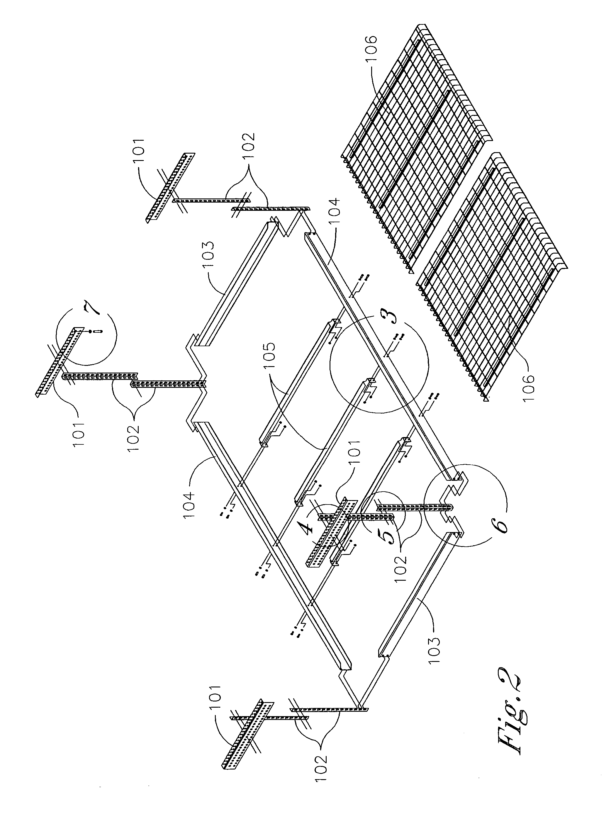
[0021]FIG. 2 shows the assembly of the present invention 100. In close-up, FIG. 3 shows the hard connection via bolts and nuts between the frame 103, 104 and a typical cross member 105. In the preferred embodiment, the angle iron for the frame 103, 104 and for the cross member 105 is standard two-sided angle iron product. In an alternate embodiment, the longitudinal beam 104 in the frame 103, 104 can be made from C-shaped-cross-section, three-sided angle iron product to provide greater strength and stiffness to the frame 103, 104. The C-shaped cross-section beam reduces the need for a...


PUM


Abstract

A hanging storage system is presented with ceiling attachment strips that can be cut to fit a variety of storage spaces, that possesses attachment brackets long enough to span two or more roof support trusses, and with a C-shaped beam on its long axis designed to permit the system to carry increased weight of stored items.

Description

FIELD OF THE INVENTION [0001] This invention relates to the area of storage systems for home and industrial use, specifically those designed to be retrofitted to existing structures, such as garages or storage units. BACKGROUND OF THE INVENTION [0002] The typical storage scenario involves identifying square footage of a building to be set aside for storage, where items will be stacked on the floor. A storage structure supported from the ceiling of a building increases the capacity of storage space by permitting items to be placed well above the floor, for example in the ceiling area of a garage. [0003] There is a long history of such storage structures in the art, including U.S. Pat. Nos. 6,715,427 and 6,435,105 to Mikich, et al. and U.S. Pat. No. 6,725,608 to Kraus. These are the most recent inventions, and they primarily address the garage ceiling storage problem. Each has their own mechanism for attachment to the ceiling rafters, and unique rack designs. [0004] The present invent...

Claims


Application Information

Patent Timeline
Patent Type & Authority Applications(United States)
IPC IPC(8): A47F5/08
CPCA47B47/02A47B96/00A47B55/02
Inventor FRATILLA, BRIAN J.
Owner EAGLE IND GRP
Why Eureka
Try Eureka