Dual backset latch assembly for lock

a latch assembly and backset technology, applied in the field of latch assembly for locks, can solve the problems of troublesome and expensive manufacturing and assembly procedures, and achieve the effect of simple and inexpensive manufacturing and assembly procedures and simplified structures

Inactive Publication Date: 2007-09-06
I TEK METAL MFG
View PDF3 Cites 4 Cited by
  • Summary
  • Abstract
  • Description
  • Claims
  • Application Information

AI Technical Summary

Benefits of technology

[0011]By such an arrangement, the backset of the latch assembly can be adjusted between two standard backset lengths (i.e., 60 mm and 70 mm) while having a simplified structure, allowing simple and inexpensive manufacturing and assembling procedures, especially the auxiliary plate and the retractor.

Problems solved by technology

However, the structure of the dual backset deadbolt assembly is complicated, leading to troublesome and expensive manufacturing and assembling procedures.

Method used


Image

  • Dual backset latch assembly for lock
  • Dual backset latch assembly for lock
  • Dual backset latch assembly for lock

Examples


Embodiment Construction

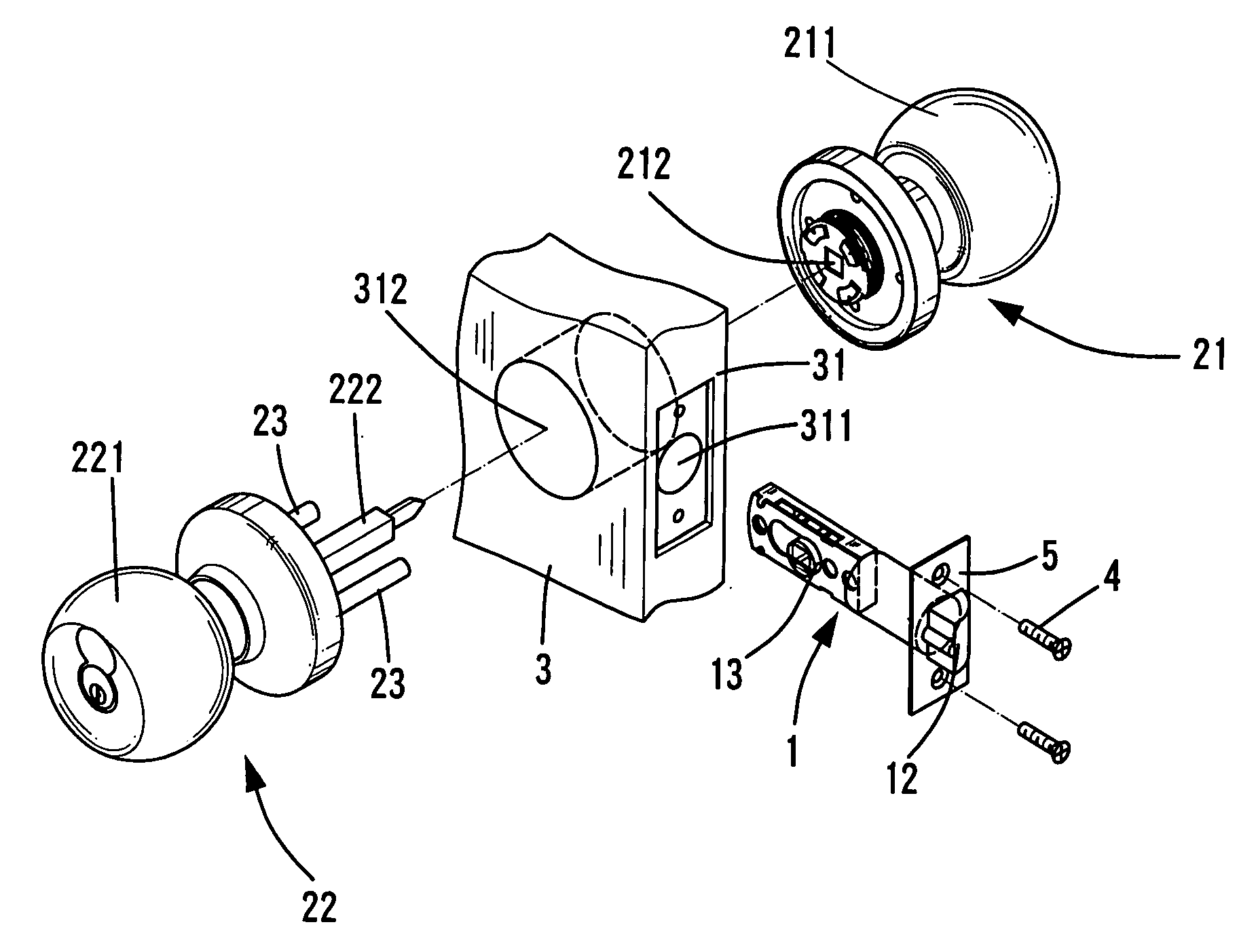
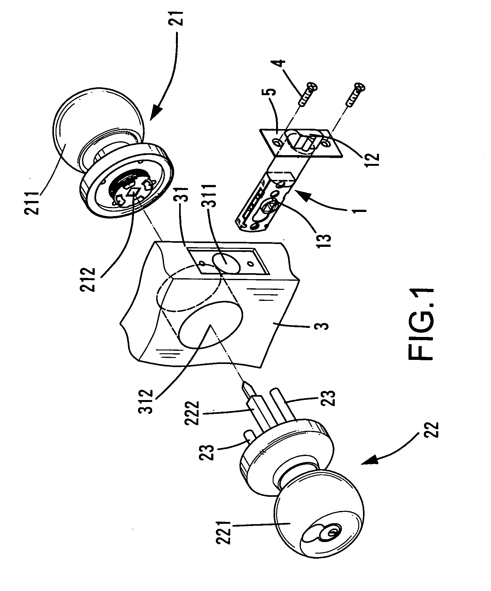
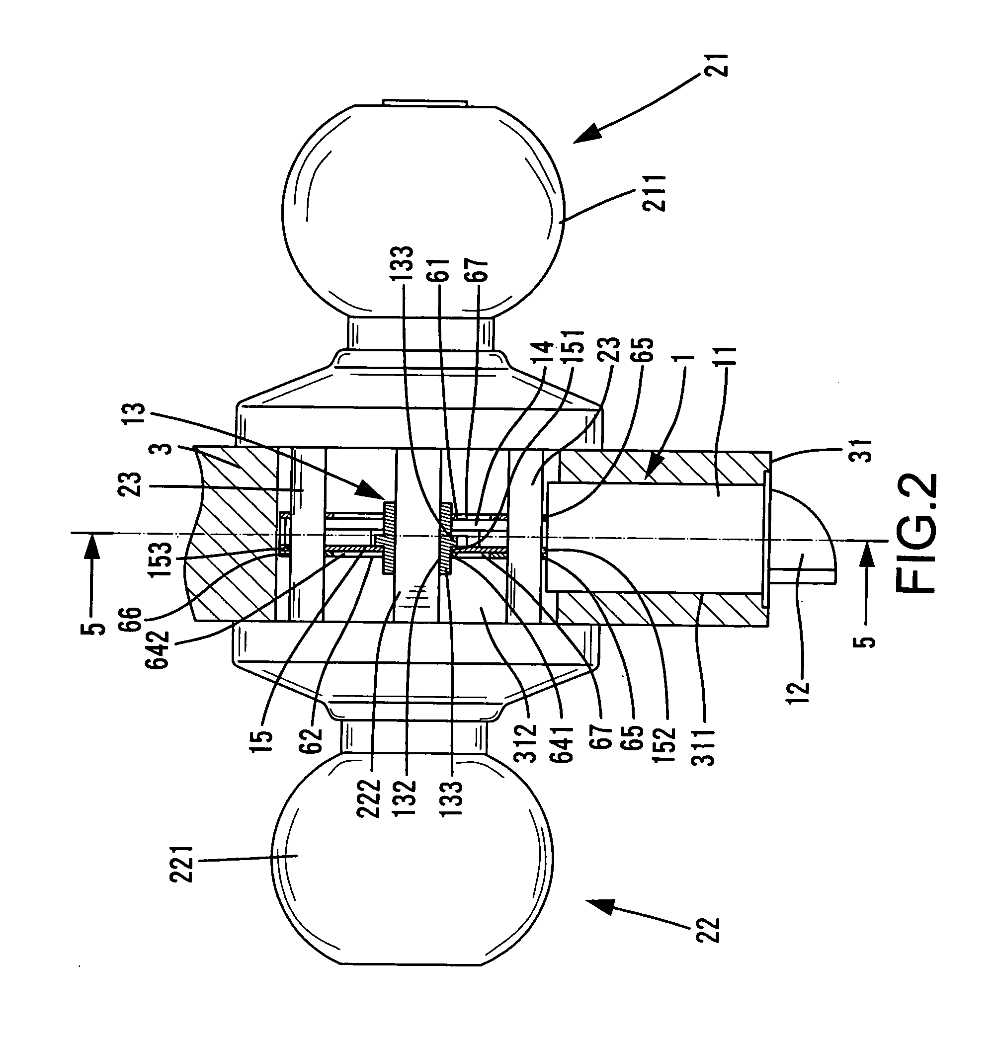
[0023]FIG. 1 is an exploded perspective view of a portion of a door 3 and a door lock with a dual backset latch assembly 1 in accordance with the present invention. FIG. 2 is a side view, partly sectioned, of the door 3 and the door lock in FIG. 1. The door lock comprises an inner assembly 21 and an outer assembly 22 respectively mounted to an inner side and an outer side of the door 3. Two mounting posts 23 are provided for mounting the inner and outer assemblies 21 and 22 to the door 3. The door 3 includes a bore 312 for accommodating elements of the inner and outer assemblies 21 and 22.

[0024]Referring to FIGS. 3 and 4, the dual backset latch assembly 1 in accordance with the present invention comprises a housing 11, a casing 6, a retractor 13, a transmission member 14, an auxiliary plate 15, and a latch 12. The latch assembly 1 is mounted into a compartment 311 in an edge 31 of the door 3 that is in communication with the bore 312 of the door. Screws 4 are extended through a face...


PUM


Abstract

A dual backset latch assembly includes a housing, a latch, a casing, a transmission member, an auxiliary plate, and a retractor. The retractor and the auxiliary plate are jointly movable for selective engagement with one of first and second mounting positions in a slot of the casing corresponding to shorter and longer backset lengths. When the retractor is in the first mounting position, a first mounting hole and a second mounting hole of the casing are respectively aligned with a first through-hole and a second through-hole of the auxiliary plate and respectively extended through by two mounting posts. When the retractor is in the second mounting position, a third mounting hole of the casing is aligned with the first through-hole of the auxiliary plate and extended through by one of the mounting posts, with the other mounting post extending through the second through-hole of the auxiliary plate.

Description

BACKGROUND OF THE INVENTION[0001]1. Field of the Invention[0002]The present invention relates to a latch assembly for a lock. More particularly, the present invention relates to a latch assembly for a lock with an adjustable backset.[0003]2. Description of the Related Art[0004]U.S. Pat. No. 5,551,736 discloses a dual backset deadbolt assembly for a cylinder lock. The dual backset deadbolt assembly is adjustable between a shorter backset length (60 mm) and a longer backset length (70 mm) and comprises a deadbolt housing, a deadbolt, an extension housing, an auxiliary mounting plate, a transmission plate, a first cam drive unit, and a second cam drive unit. The second can drive unit is movable between two positions for adjusting the backset. However, the structure of the dual backset deadbolt assembly is complicated, leading to troublesome and expensive manufacturing and assembling procedures.BRIEF SUMMARY OF THE INVENTION[0005]A dual backset latch assembly for a lock in accordance wi...

Claims


Application Information

Patent Timeline
Patent Type & Authority Applications(United States)
IPC IPC(8): E05C1/00
CPCE05B63/06E05B55/005Y10T292/06
Inventor SHEN, MU-LIN
Owner I TEK METAL MFG
Why Eureka
Try Eureka