

Rotary electric machine
- Summary
- Abstract
- Description
- Claims
- Application Information
AI Technical Summary
Benefits of technology
Problems solved by technology
Method used
Image

Examples
embodiment 1
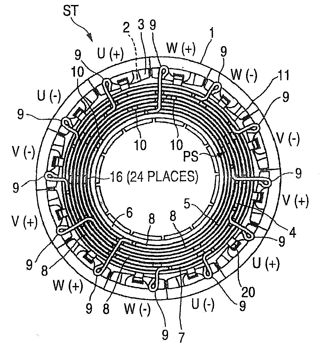
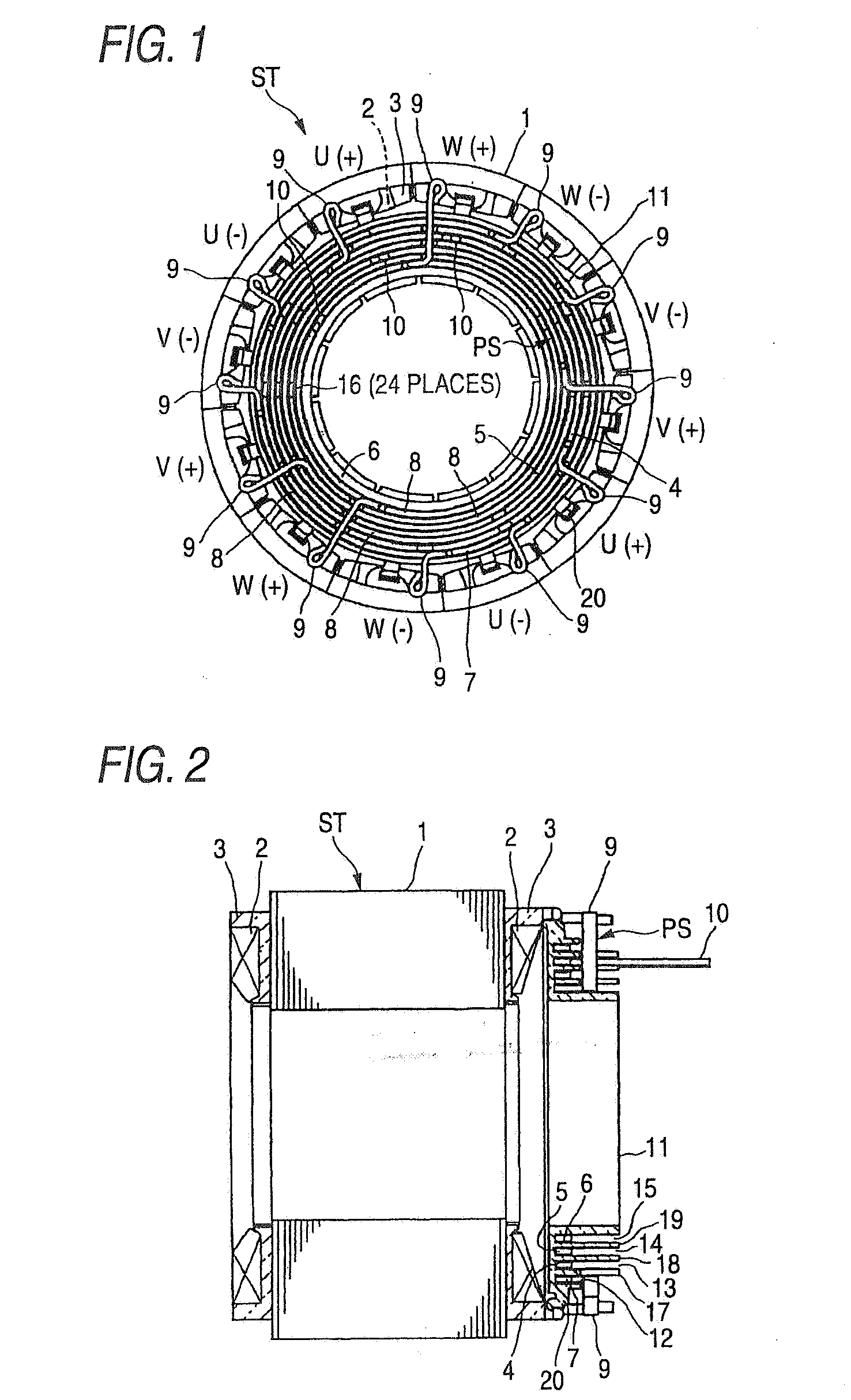
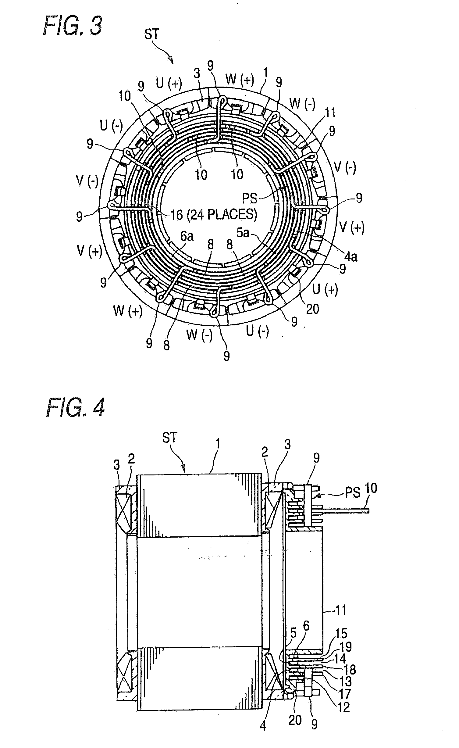
[0027]Embodiment 1 according to this invention will be described with reference to FIG. 1 through FIG. 10. Of these figures, FIG. 1 is an end face view showing a state where the configuration of a stator in a Y-connection in Embodiment 1 is seen in the axial direction thereof, FIG. 2 is a vertical sectional view of the stator shown in FIG. 1, FIG. 3 is an end face view showing a state where the configuration of a stator in a delta connection in Embodiment 1 is seen in the axial direction thereof, FIG. 4 is a vertical sectional view of the stator shown in FIG. 3, FIG. 5 is an end face view showing a state where the configuration of a simple holding member in Embodiment 1 is seen in the axial direction thereof, FIG. 6 is a partial sectional view taken along line VI-VI indicated in FIG. 5, FIG. 7 is an end face view showing a state where the configuration of a conductive member of U-phase for the Y-connection in Embodiment 1 is seen in the axial direction thereof, FIG. 8 is an end face...
embodiment 2
[0063]Embodiment 2 according to this invention will be described with reference to FIG. 11 through FIG. 17. Of these figures, FIG. 11 is an end face view showing a state where the configuration of a stator in a Y-connection in the case of 8 poles and 12 slots in Embodiment 2 is seen in the axial direction thereof, FIG. 12 is an end face view showing a state where the configuration of a stator in a delta connection in the case of 8 poles and 12 slots in Embodiment 2 is seen in the axial direction thereof, FIG. 13 is an end face view showing a state where the configuration of a simple holding member in Embodiment 2 is seen in the axial direction thereof, FIG. 14 is an end face view showing a state where the configuration of a conductive member of U-phase for the Y-connection in Embodiment 2 is seen in the axial direction thereof, FIG. 15 is an end face view showing a state where the configuration of a conductive member of U-phase for the delta connection in Embodiment 2 is seen in the...
PUM
 Abstract
Description
Claims
Application Information