Magnetic resonance imaging apparatus and magnetic resonance imaging method

Inactive Publication Date: 2007-09-06
TOSHIBA MEDICAL SYST CORP
View PDF11 Cites 25 Cited by
  • Summary
  • Abstract
  • Description
  • Claims
  • Application Information

AI Technical Summary

Benefits of technology

[0031] The magnetic resonance imaging apparatus and the magnetic resonance imaging method as described above make it possible to obtain an image with highly accurate motion correction by acquiring motion signals sufficient for observing motion amount

Problems solved by technology

However, in the breath-holding imaging, the imaging is only performed during a breath-holding period and there is a limitation on the resolution.
In addition, there is a fear in the degree of stability of the breath-holding.
However, there is a problem in that this synchronous imaging method with use of the synchronous signal obtained by the expansion and contraction sensor or the pressure sensor has insufficient accuracy.
However, the navigator method for collecting the navigator signal under a condition different from the data collection condition for imaging has two major problems.
The first problem resides in that the amount of breath-related shift of the target area of the imaging (the heart) and the amount of shift of the area to be observed by the navigator signal (the diaphragm) have relevance but are not completely the same to each other.
Therefore, the amount of shift of the heart is estimated from the amount of shift of the diaphragm, which is a cause of decreasing the accuracy.
In addition, a ratio between the amount of breath-related shift of the heart and the amount of shift of the diaphragm varies between individuals and changes depending on the state of breathing even in the same object, and it is therefore difficult to obtain a stable image.
The sec

Method used


Image

  • Magnetic resonance imaging apparatus and magnetic resonance imaging method
  • Magnetic resonance imaging apparatus and magnetic resonance imaging method
  • Magnetic resonance imaging apparatus and magnetic resonance imaging method

Examples


first embodiment

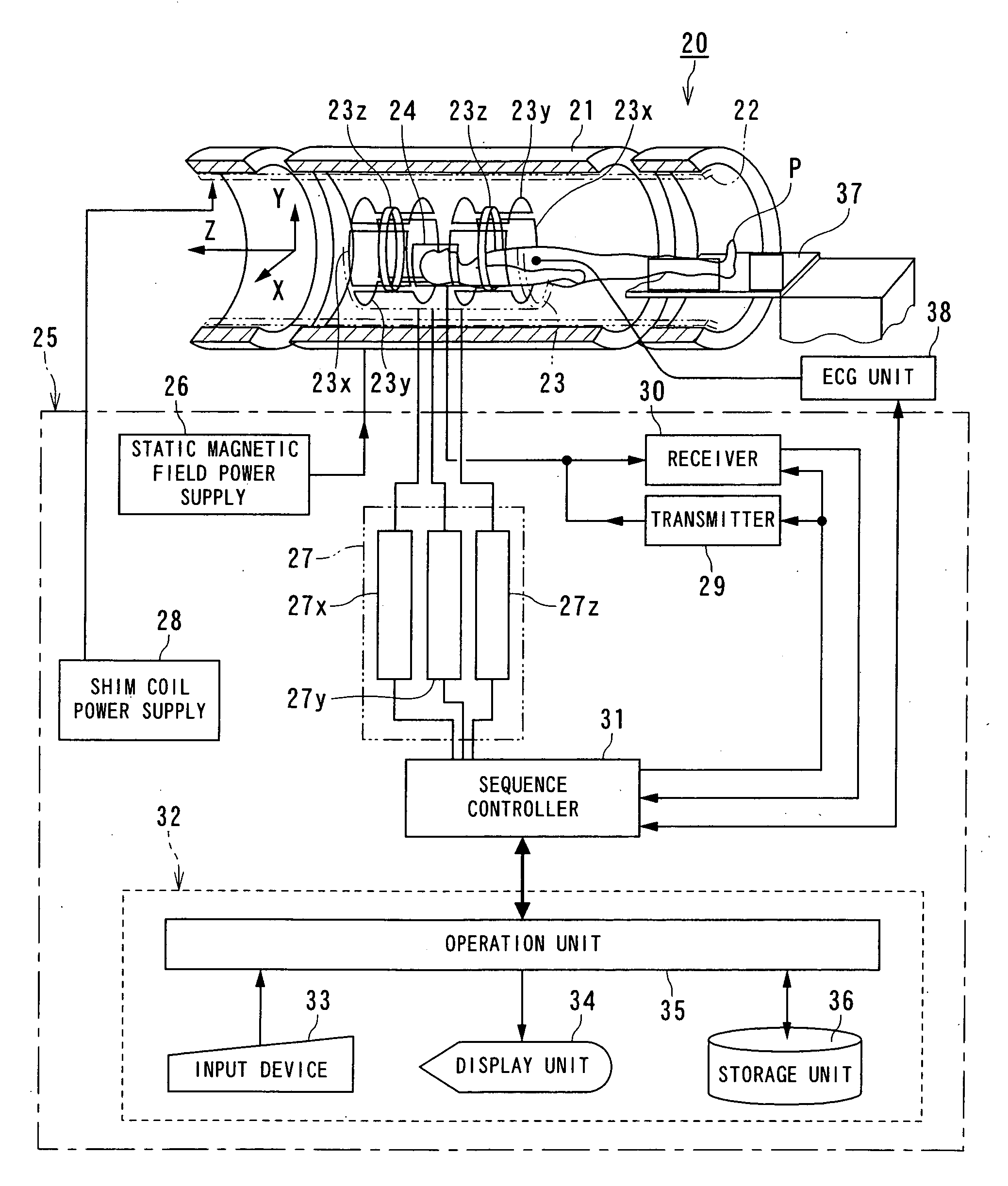
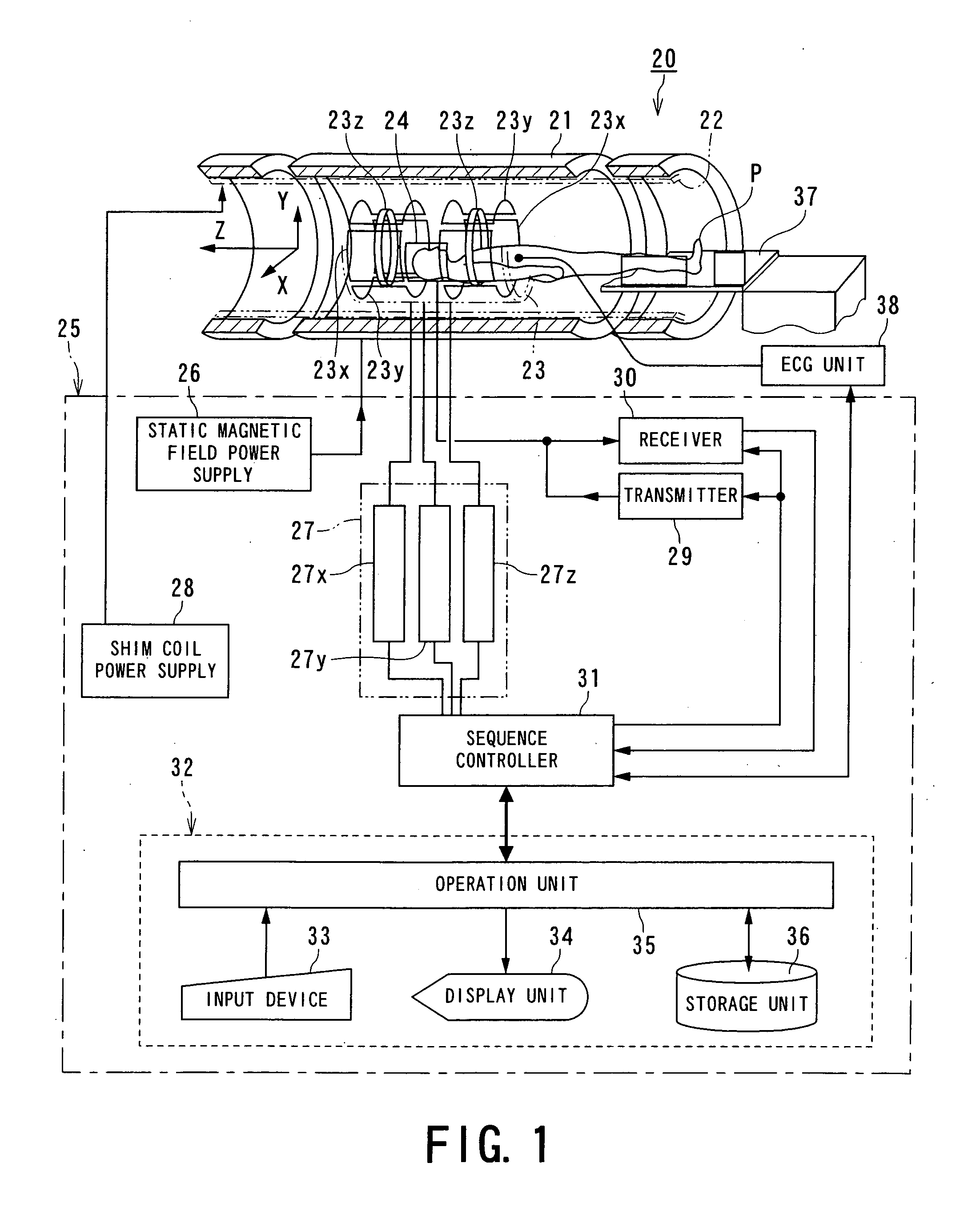
[0058]FIG. 1 is a block diagram showing a magnetic resonance imaging apparatus according to the present invention.

[0059] A magnetic resonance imaging apparatus 20 shown in FIG. 1 includes a static field magnet 21 for generating a static magnetic field, a shim coil 22 arranged inside the static field magnet 21 which is cylinder-shaped, a gradient coil unit 23 and a RF coil 24. The static field magnet 21, the shim coil 22, the gradient coil unit 23 and the RF coil 24 are built in a gantry (not shown).

[0060] The magnetic resonance imaging apparatus 20 also includes a control system 25. The control system 25 includes a static magnetic field power supply 26, a gradient power supply 27, a shim coil power supply 28, a transmitter 29, a receiver 30, a sequence controller 31 and a computer 32. The gradient power supply 27 of the control system 25 includes an X-axis gradient power supply 27x, a Y-axis gradient power supply 27y and a Z-axis gradient power supply 27z. The computer 32 includes ...


PUM


Abstract

An MRI apparatus includes an imaging signal acquisition unit, a motion signal acquisition unit, a motion amount determination unit, a motion correction unit and an image reconstruction unit. The imaging signal acquisition unit acquires MR signals as imaging signals. The motion signal acquisition unit repetitively acquires MR signals having PE amount less than that of the imaging signals as motion signals. The motion amount determination unit obtains a motion amount using the motion signals. The motion correction unit performs correction processing of the imaging signals in accordance with the motion amount. The image reconstruction unit reconstructs an image using the imaging signals after the correction processing.

Description

BACKGROUND OF THE INVENTION [0001] 1. Field of the Invention [0002] The present invention relates to a magnetic resonance imaging apparatus and a magnetic resonance imaging method which generate gradient magnetic fields on an imaging area formed in a static magnetic field, resonates nuclear spins in the object set in the imaging area magnetically by transmitting radio frequency signals and reconstructs an image of the object by using nuclear magnetic resonance signals generated due to an excitation, and more particularly, to a magnetic resonance imaging apparatus and a magnetic resonance imaging method in which influence of motion of the object on an image is reduced by correction. [0003] 2. Description of the Related Art [0004] An MRI (Magnetic Resonance Imaging) apparatus is an apparatus which generates gradient magnetic fields by gradient coils on an imaging area of an object set in a cylindrical static field magnet for producing a static magnetic field, resonates nuclear spins i...

Claims


Application Information

Patent Timeline
IPC IPC(8): G01V3/00
CPCG01R33/546G01R33/5614G01R33/5676G01R33/56509G01R33/56518G01R33/5635
Inventor YUI, MASAOKASSAI, YOSHIMORIKUHARA, SHIGEHIDE
Owner TOSHIBA MEDICAL SYST CORP
Why Eureka
Try Eureka