
Mouth Switch Mechanism for Operation Microscope

a technology of operation microscope and mouth switch, which is applied in the field of mouth switch for controlling an operation microscope, can solve the problems and achieve the effect of increasing the risk of causing erroneous operation

Active Publication Date: 2007-09-06
MITAKA KOHKI
View PDF5 Cites 6 Cited by
  • Summary
  • Abstract
  • Description
  • Claims
  • Application Information

AI Technical Summary

Benefits of technology

[0003] According to such a conventional technique, the footswitch must be used to select and control one of the functions of the operation microscope. As the number of functions of the operation microscope increases, the number of control switches arranged for the footswitch must be increased to increase the risk of causing erroneous operation. For this

Problems solved by technology

As the number of functions of the operation microscope increases, the number of control switches arranged for the footswitch must be increased to increase the risk of causing erroneous operation.

Method used


Image

  • Mouth Switch Mechanism for Operation Microscope
  • Mouth Switch Mechanism for Operation Microscope
  • Mouth Switch Mechanism for Operation Microscope

Examples


Embodiment Construction

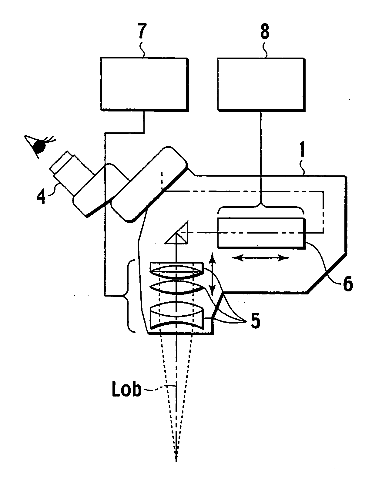
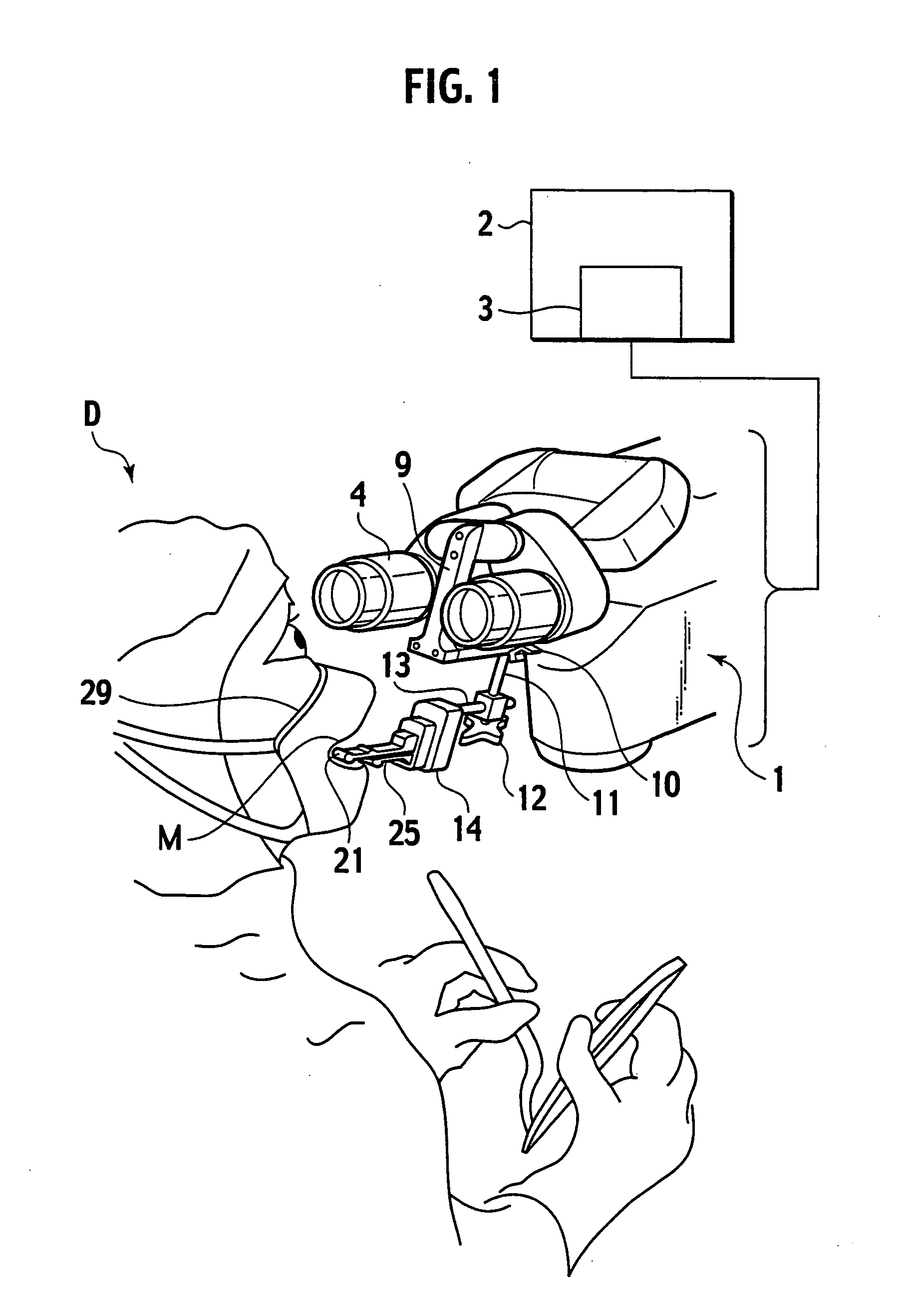
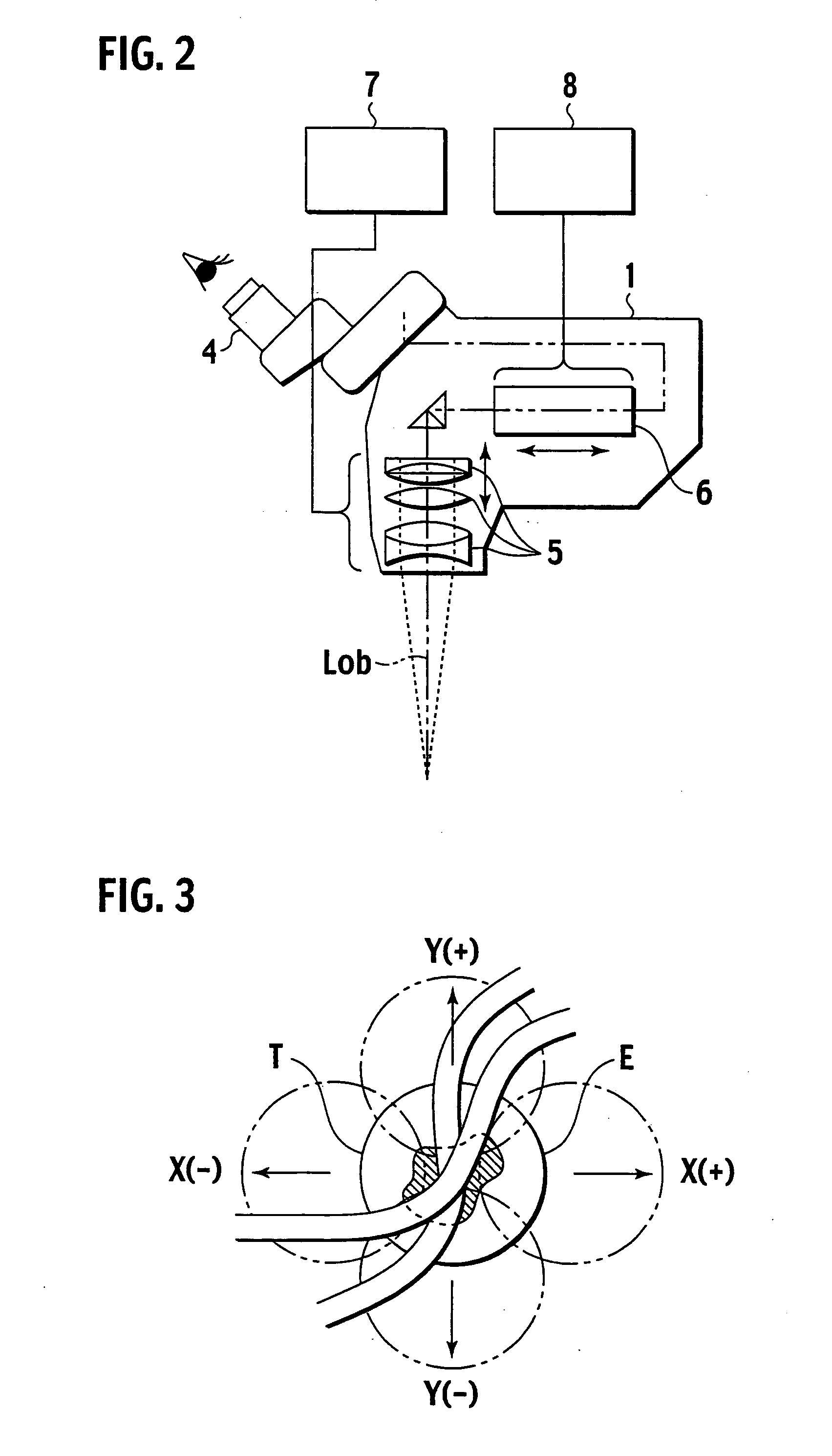
[0016] An embodiment of the present invention will be explained with reference to FIGS. 1 to 9. An operation microscope 1 is in an operation room and is supported with a support mechanism 2 such as a stand unit. The support mechanism 2 has an X-Y driver 3 serving as an electric control mechanism that can move the operation microscope 1 as a whole in an imaginary plane defined by intersecting directions (X- and Y-axis directions). Namely, an optical axis Lob of an objective lens of the operation microscope 1 is translated in directions perpendicular to the optical axis to change a field of view so that a focal plane (focal depth range) of the objective lens comes in an affected part. According to the embodiment, a field of view is represented with a horizontal plane in which X and Y axes orthogonally crosses.

[0017] The operation microscope 1 is a stereo microscope having two eyepieces 4. As shown in FIG. 2, the operation microscope 1 includes a focusing lens 5 in a vertical directio...


PUM


Abstract

A mouth switch is provided for a multifunction operation microscope (1). Signals to be outputted to the operation microscope can be switched from one provided when only a long main lever (21) is held with a mouth (lips, teeth, and the like) to another provided when a sub-lever (25) is held together with the main lever. Even if the number of functions to control increases, the mouth switch can cope with them. The mouth switch can change signals through the simple operation of holding the levers with a mouth, and therefore, possibility of an operation error can be reduced. As a changeover switch (22) is OFF, the mouth switch provides four kinds of signals including focus-up, focus-down, zoom-in, and zoom-out signals, and as for ON state, other four kinds of signals relating to X(+) direction, X(−) direction, Y(+) direction, and Y(−) direction for shifting field of view are provided.

Description

TECHNICAL FIELD [0001] The present invention relates to a mouth switch for controlling an operation microscope. BACKGROUND TECHNOLOGY [0002] In the fields of brain surgery, cardiac surgery, and the like, an operation microscope is used to observe an affected part and conduct an operation in an enlarged field of view. The operation microscope used for such surgery has a plurality of functions such as focus adjustment and zoom adjustment. An operator keeps his or her eyes in contact with eyepieces of the operation microscope and uses both of his or her hands for the operation. Accordingly, the functions of the microscope are generally changed from one to another with a footswitch placed on the floor. The footswitch is provided with a plurality of control switches that are manipulated by the sole of a foot of the operator to change the functions from one to another. DISCLOSURE OF INVENTION [0003] According to such a conventional technique, the footswitch must be used to select and cont...

Claims


Application Information

Patent Timeline
IPC IPC(8): G02B21/00A61B19/00G02B21/26
CPCG02B21/0012A61B19/5223A61B90/20
Inventor NAKAMURA, KATSUSHIGE
Owner MITAKA KOHKI
Learn More