System for and method of protecting an integrated circuit from over currents

a technology of integrated circuits and protection methods, applied in the field of contact detectors, can solve problems such as excessive current draw, damage to the functional disconnect of contact detectors, and the inability to maintain the function of contact detectors, so as to avoid overcurrent draw, and leave more contact detectors for subsequent operation

Inactive Publication Date: 2007-09-06
APPLE INC
View PDF99 Cites 19 Cited by
  • Summary
  • Abstract
  • Description
  • Claims
  • Application Information

AI Technical Summary

Benefits of technology

[0006] Embodiments of the present invention protect contact detectors, such as fingerprint sensors, from damage stemming from electrostatic discharge (ESD) events, mechanical damage, and similar events. Electrostatic charges stored on a finger, body of a user, or both can be discharged to devices that the finger contacts. This discharge often triggers a latch-up condition, which in turn can draw excessive current. Embodiments of the present invention have a power switch, insulated from ESD events, that disconnects power to portions of the contact detector when an over current condition is detected on the contact sensor. Embodiments of the present invention also include a state machine for recovering from latch-up and disconnecting portions of the device that are permanently damaged.

Problems solved by technology

This discharge often triggers a latch-up condition, which in turn can draw excessive current.
Damaged areas of the contact detector are functionally disconnected from the contact detector.
Thus, rather than disconnecting a large block of electronics when only a small area of the contact detector is damaged, the small area is disconnected using its dedicated power switch, thus leaving more of the contact detector for subsequent functioning.
Undamaged blocks continue to operate.

Method used


Image

  • System for and method of protecting an integrated circuit from over currents
  • System for and method of protecting an integrated circuit from over currents
  • System for and method of protecting an integrated circuit from over currents

Examples


Embodiment Construction

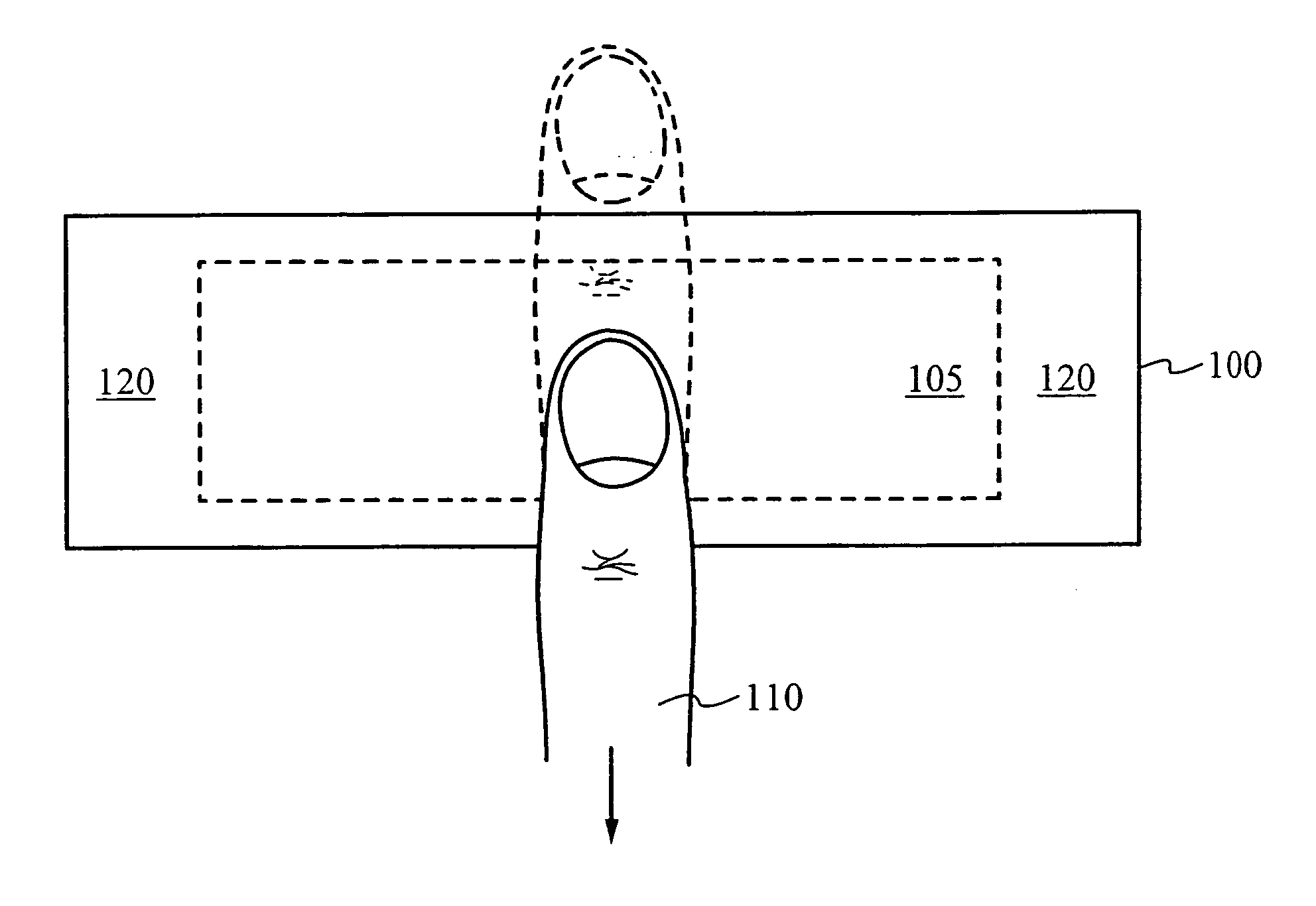
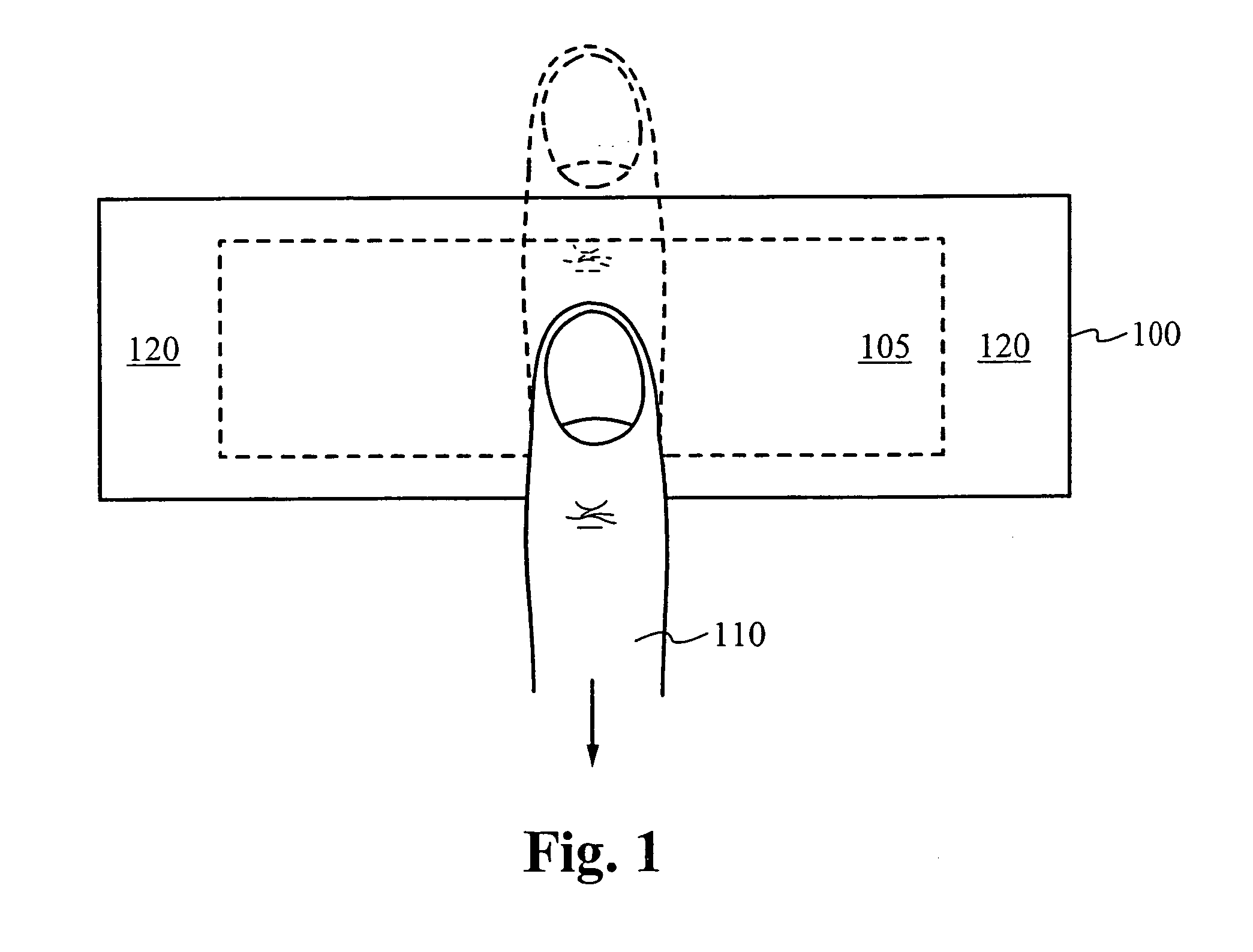
[0027] The present invention is directed to protecting contact detectors that have exposed portions, such as the portion of a finger sensor used to capture finger images. These portions are exposed in that they are contacted to capture image data or other data and thus contain or overlie electronics used to process the image or other data. Because these portions come into contact with fingers and materials that can carry electrostatic charges, these portions are necessarily vulnerable to latch-up, which can result in the generation of excessive current that can damage the integrated circuits that form the contact detector. The portions are also susceptible to mechanical and other damage. While much of the discussion that follows focuses on finger image sensors, it will be appreciated that other contact detectors and other types of integrated circuits are able to benefit from the present invention.

[0028]FIG. 1 shows a finger 110 being swiped along a finger swipe sensor 100 in accord...


PUM


Abstract

A contact detector having power switches for disconnecting power to portions of the contact sensor when an over current is detected is disclosed. The power switches thus protect the contact sensor from over-current as the result of latch-up or other current-generating conditions. These current-generating conditions are often the result of ESD events on a surface of the contact detector. A contact detector comprises an exposed surface for detecting the presence of an object, an insulating surface, and a protection element disposed under the insulating surface for controlling power to the contact detector. The protection element is configured to disconnect power to the contact detector when a current to the contact detector is detected above a threshold. Preferably, the contact detector is a finger swipe sensor, but it can be a finger placement sensor or any other type of device that functions on contact with a finger or other patterned object.

Description

RELATED APPLICATION [0001] This application claims priority under 35 U.S.C. § 119(e) of the co-pending U.S. provisional patent application Ser. No. 60 / 669,520, filed Apr. 8, 2005, and titled “Dynamically Illuminated Biometric Sensor, Modular Packaging Technology, and Over-Current Chip Protection Architecture,” which is hereby incorporated by reference.FIELD OF THE INVENTION [0002] This invention is related to contact detectors. More specifically, this invention is related to systems for and methods of protecting contact detectors from excessive currents and resulting damage. BACKGROUND OF THE INVENTION [0003] Integrated circuits, especially those with surfaces that are exposed to human contact, are susceptible to damage resulting from electrostatic discharge (ESD), short circuits, mechanical damage, and similar occurrences. These occurrences can induce latch-up conditions in at least a portion of the integrated circuit or can produce other damage that results in excessive or over cu...

Claims


Application Information

Patent Timeline
Patent Type & Authority Applications(United States)
IPC IPC(8): H01R9/22
CPCG06K9/00053G06V40/1329
Inventor ZABRODA, OLEKSIYCHENG, ERICSON W.NGO, HUNG XUAN
Owner APPLE INC
Why Eureka
Try Eureka