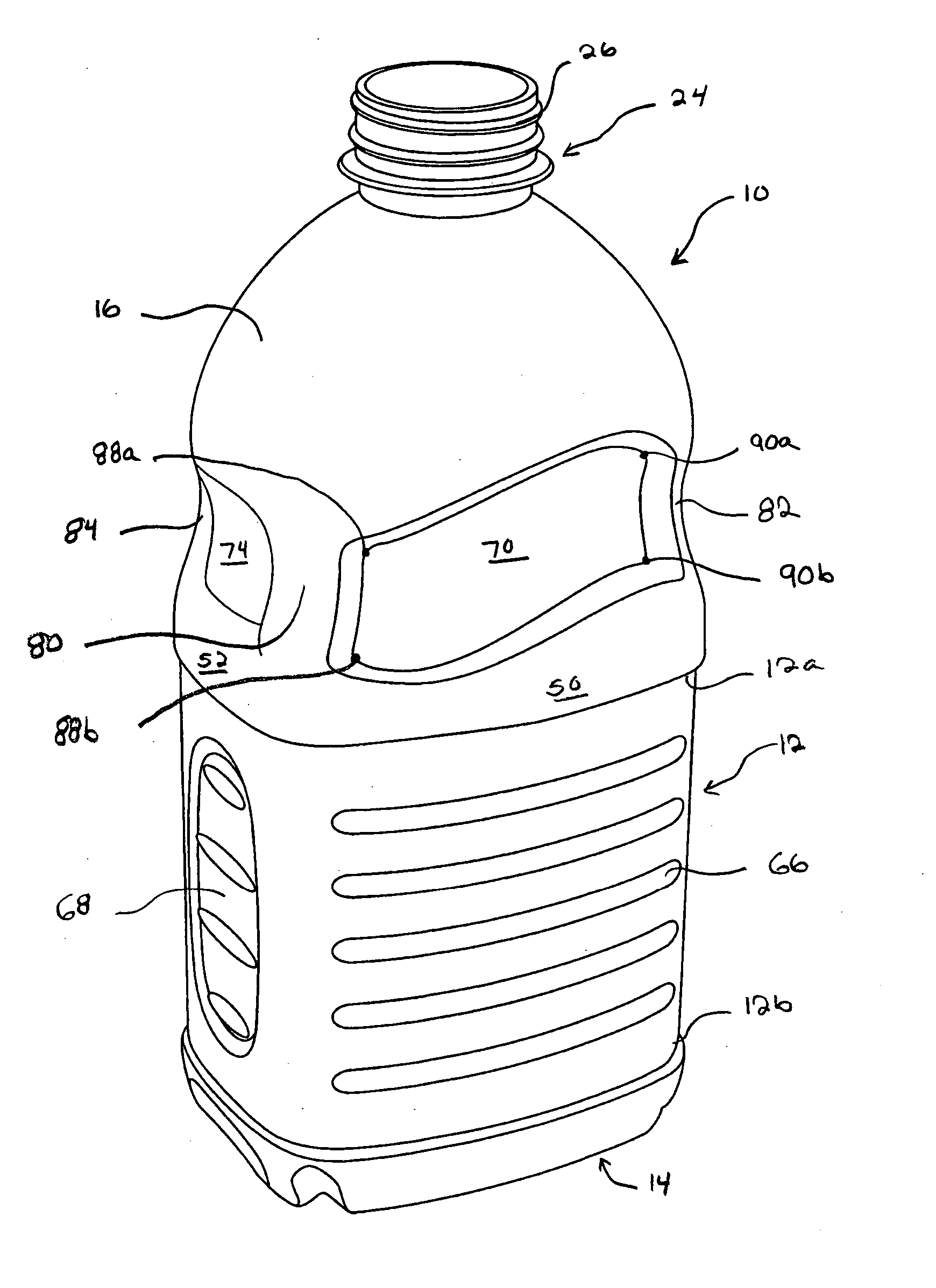
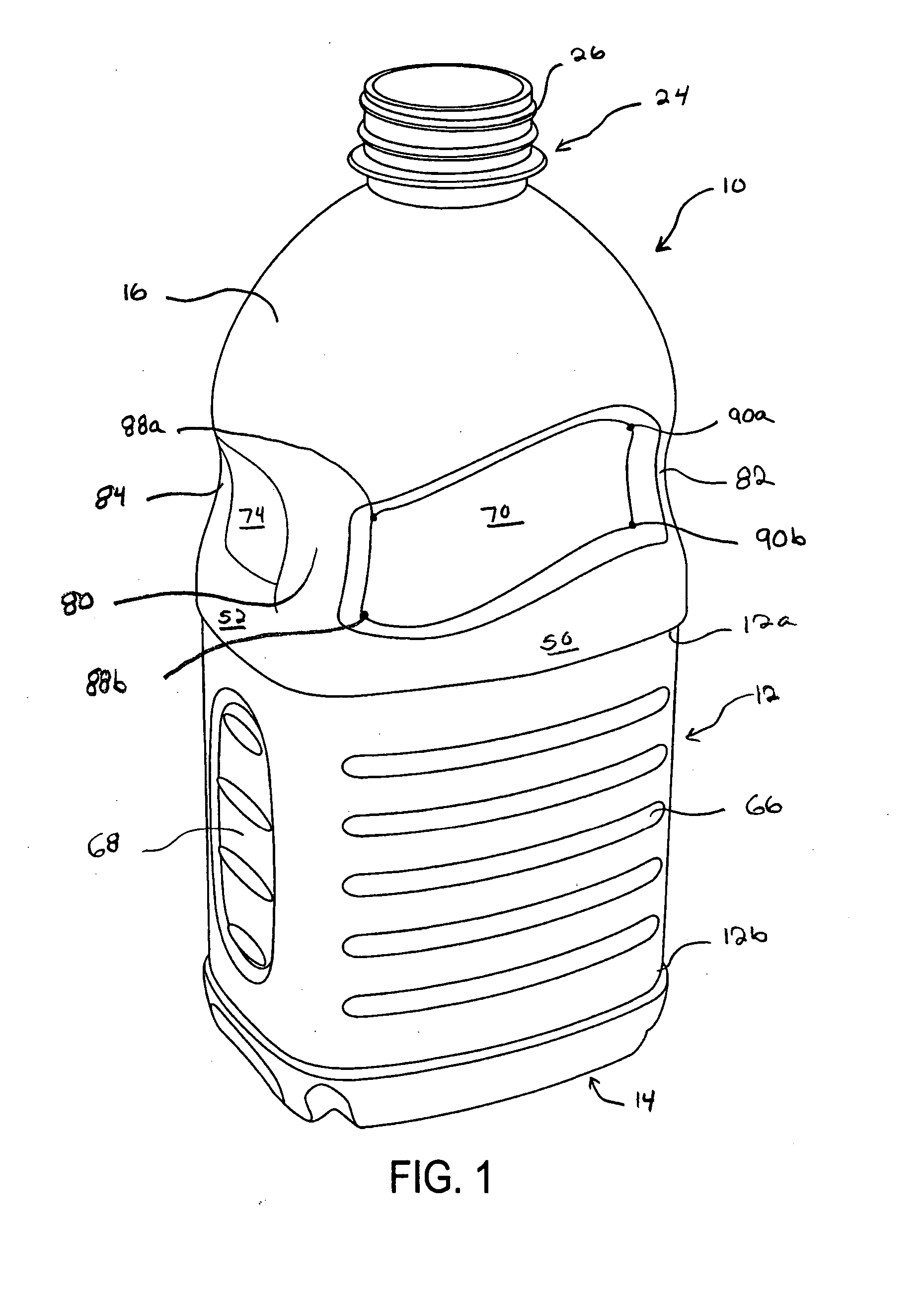
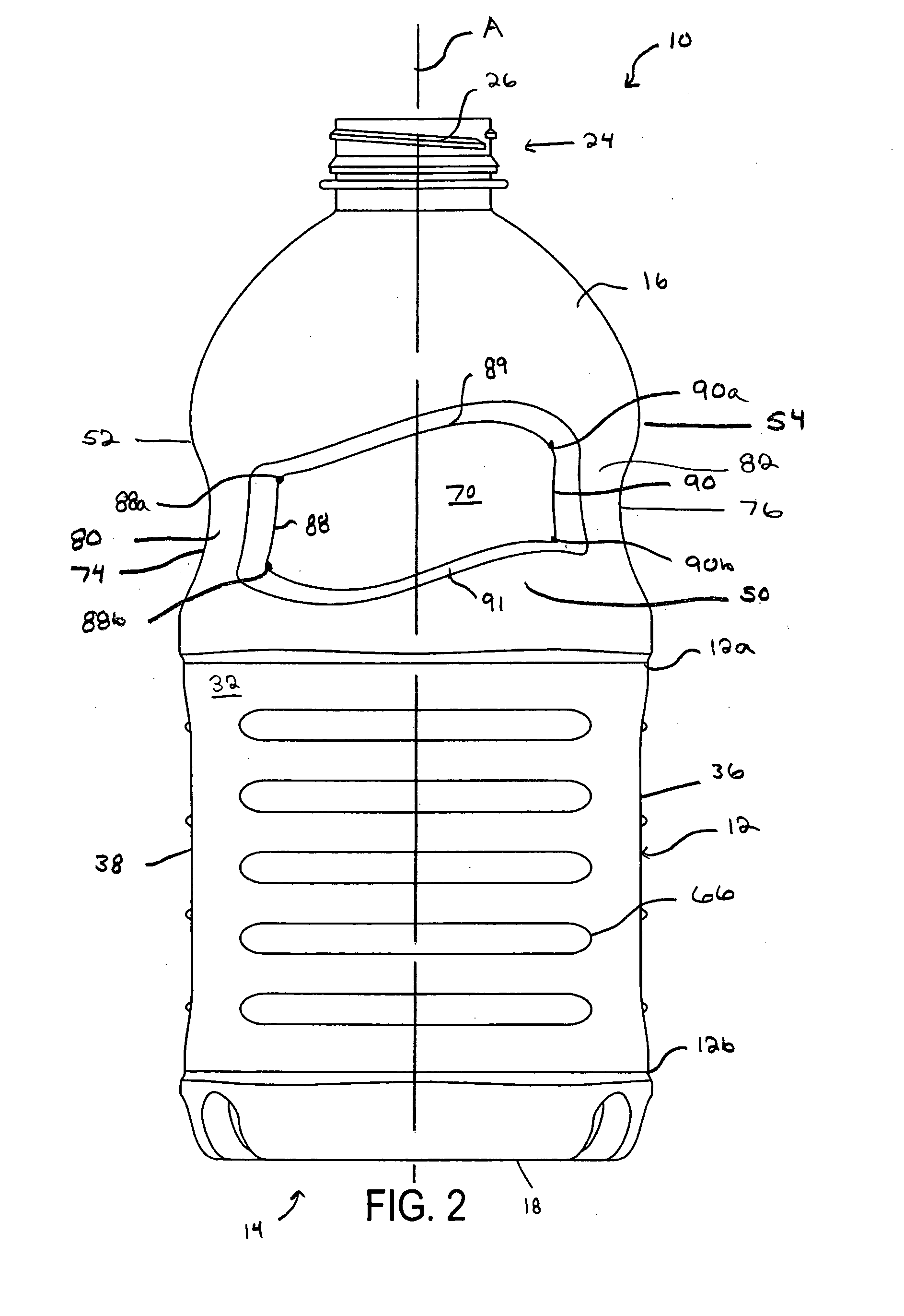
Plastic container

a technology for plastic containers and containers, applied in the field of plastic containers, can solve the problems of reducing affecting the appearance and/or ergonomics of the container, and hot-filled containers often experience internal forces, etc., and achieve the effect of increasing the top load strength of the container

Active Publication Date: 2007-09-13
GRAHAM PACKAGING CO LP
View PDF15 Cites 23 Cited by
  • Summary
  • Abstract
  • Description
  • Claims
  • Application Information

AI Technical Summary

Benefits of technology

[0006] The present invention provides a plastic container including a unique, multifunctional grip component that provides an area for branding or other aesthetic enhancement, and also increases the top load strength of the container.

Problems solved by technology

For example, hot-filled containers often experience internal forces, such as vacuum forces, that occur as a result of shrinkage of the container's contents as they cool.
In addition, plastic containers are often subject to considerable top loads during storage and transportation, for example, as a result of stacking several layers of containers on top of one another.
Many of the known structures, however, detract from the appearance and / or ergonomics of the container.

Method used


Image

  • Plastic container
  • Plastic container
  • Plastic container

Examples


example

[0035] A model of a 64 oz container according to the present invention was compared to a model of a conventional 64 oz container using computerized Finite Element Analysis (FEA). The analysis used common and uniform wall thickness mapping for both models. The analysis was run using non-linear PET material properties for both models. FIG. 7 is a graph demonstrating the results of the analysis. The X-axis of the graph represents vertical deflection of the container (i.e., along its longitudinal axis) in inches. The Y-axis represents the amount of top load force applied to the container in pounds. Line B represents the force vs. deflection curve for the conventional container, and line C represents the force vs. deflection curve for the container according to the present invention. Based on the output of the FEA study, the 64 oz container according to the present invention demonstrated a top load capacity that is approximately 16% greater than that of the conventional 64 oz container. ...


PUM


Abstract

A plastic container comprises a sidewall including an upper end and a lower end, a base connected to the lower end of the sidewall, a dome connected to the upper end of the sidewall, the dome including a finish portion adapted to receive a closure, first and second primary grip panels recessed into the dome, first and second secondary grip panels recessed into the dome, and a plurality of support columns located on the dome, with a support column located between each adjacent pair of primary and secondary grip panels.

Description

CROSS-REFERENCE TO RELATED APPLICATIONS [0001] The present application claims priority of U.S. Provisional Application No. 60 / 780,826, filed on Mar. 10, 2006, the entire contents of which are incorporated herein by reference.BACKGROUND OF THE INVENTION [0002] 1. Field of the Invention [0003] The present invention relates generally to plastic containers, and more particularly, to plastic containers including grip features. [0004] 2. Related Art [0005] Containers, and particularly plastic containers, are subjected to varying forces during filling, sealing, and storage. For example, hot-filled containers often experience internal forces, such as vacuum forces, that occur as a result of shrinkage of the container's contents as they cool. In addition, plastic containers are often subject to considerable top loads during storage and transportation, for example, as a result of stacking several layers of containers on top of one another. Containers typically include reinforcing structures t...

Claims


Application Information

Patent Timeline
Patent Type & Authority Applications(United States)
IPC IPC(8): B65D90/02
CPCB65D1/0223B65D2501/0081B65D2501/0036B65D79/005B65D23/102B65D79/0081
Inventor HEISNER, DAVIDDEGROFF, JAMIESHEETS, PHILIP
Owner GRAHAM PACKAGING CO LP
Why Eureka
Try Eureka