Optical scanning device and image forming apparatus

a scanning device and image forming technology, applied in the field of optical scanning devices, can solve the problems of inability to produce high-quality images, and inability to vary the magnification of images

Inactive Publication Date: 2007-09-13
RICOH KK
View PDF6 Cites 14 Cited by
  • Summary
  • Abstract
  • Description
  • Claims
  • Application Information

AI Technical Summary

Problems solved by technology

However, the known apparatus has a problem in that the image magnification varies from apparatus to apparatus due to variations in the lens characteristics.
Thus, the scanning position on an image surface of the photoreceptor shifts, and a magnification error in the main-scanning direction occurs; thus, it is impossible produce a high-quality image.
In an apparatus that uses multiple laser beams and multiple lenses to produce an image of multiple colors, magnification errors thereof cause color shifting; thus, it is impossible to produce a high-quality image.
In order to maintain the image quality in such a situation, it is necessary to frequently perform measurement between two points and perform correction, but it is difficult to change the pixel clock frequency during continuous printing.
In a color-image forming apparatus, particularly, an apparatus in which the scanning direction of at least one light beam is opposite to that of other light beams, the magnification error directly leads to color shifting.

Method used


Image

  • Optical scanning device and image forming apparatus
  • Optical scanning device and image forming apparatus
  • Optical scanning device and image forming apparatus

Examples


Embodiment Construction

[0032] It will be understood that if an element or layer is referred to as being “on”, “against”, “connected to” or “coupled to” another element or layer, then it can be directly on, against, connected or coupled to the other element or layer, or intervening elements or layers may be present. In contrast, if an element is referred to as being “directly on”, “directly connected to” or “directly coupled to” another element or layer, then there are no intervening elements or layers present. Like numbers referred to like elements throughout. As used herein, the term “and / or” includes any and all combinations of one or more of the associated listed items.

[0033] Spatially relative terms, such as “beneath”, “below”, “lower”, “above”, “upper” and the like may be used herein for ease of description to describe one element or feature's relationship to another element(s) or feature(s) as illustrated in the figures. It will be understood that the spatially relative terms are intended to encomp...


PUM


Abstract

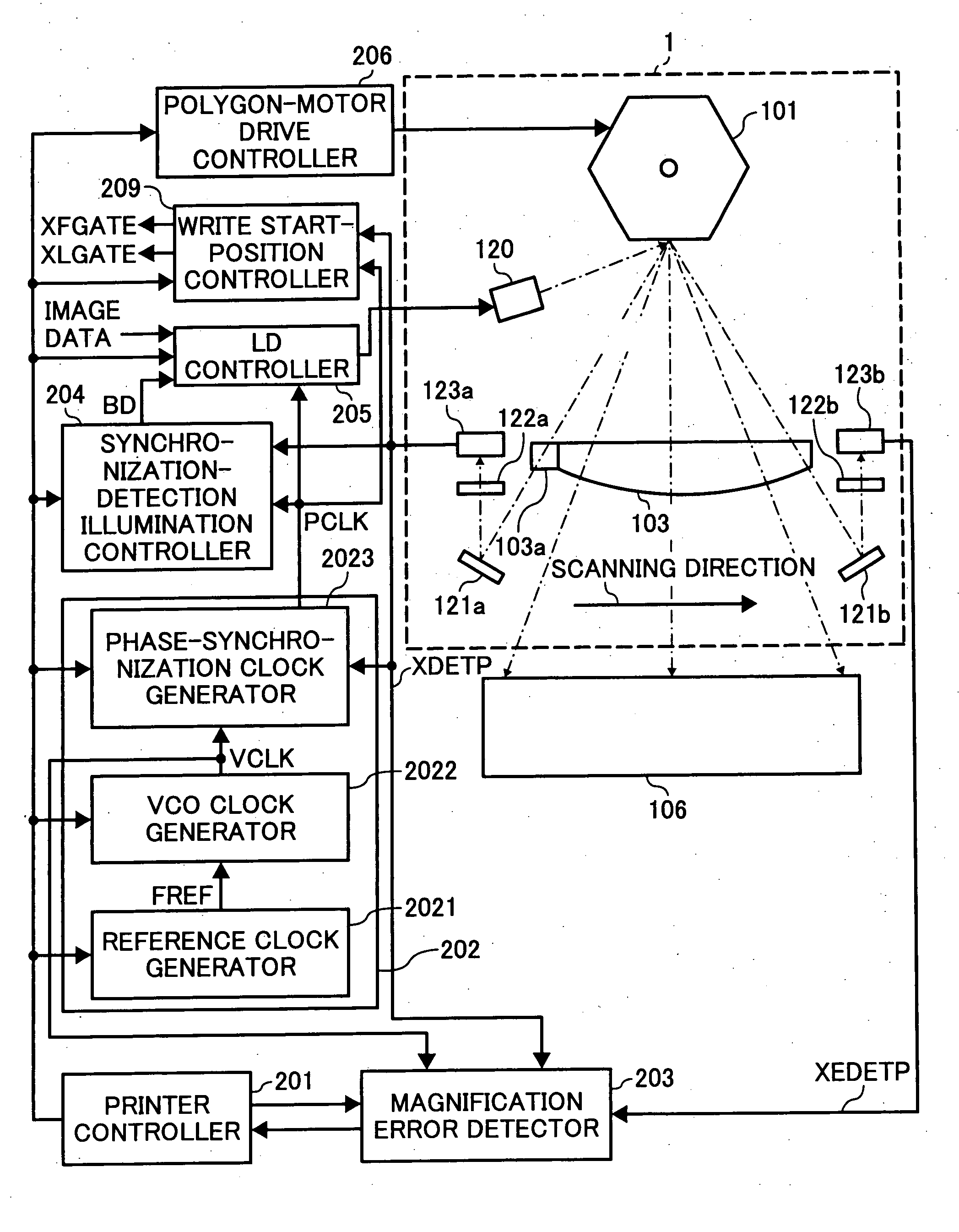
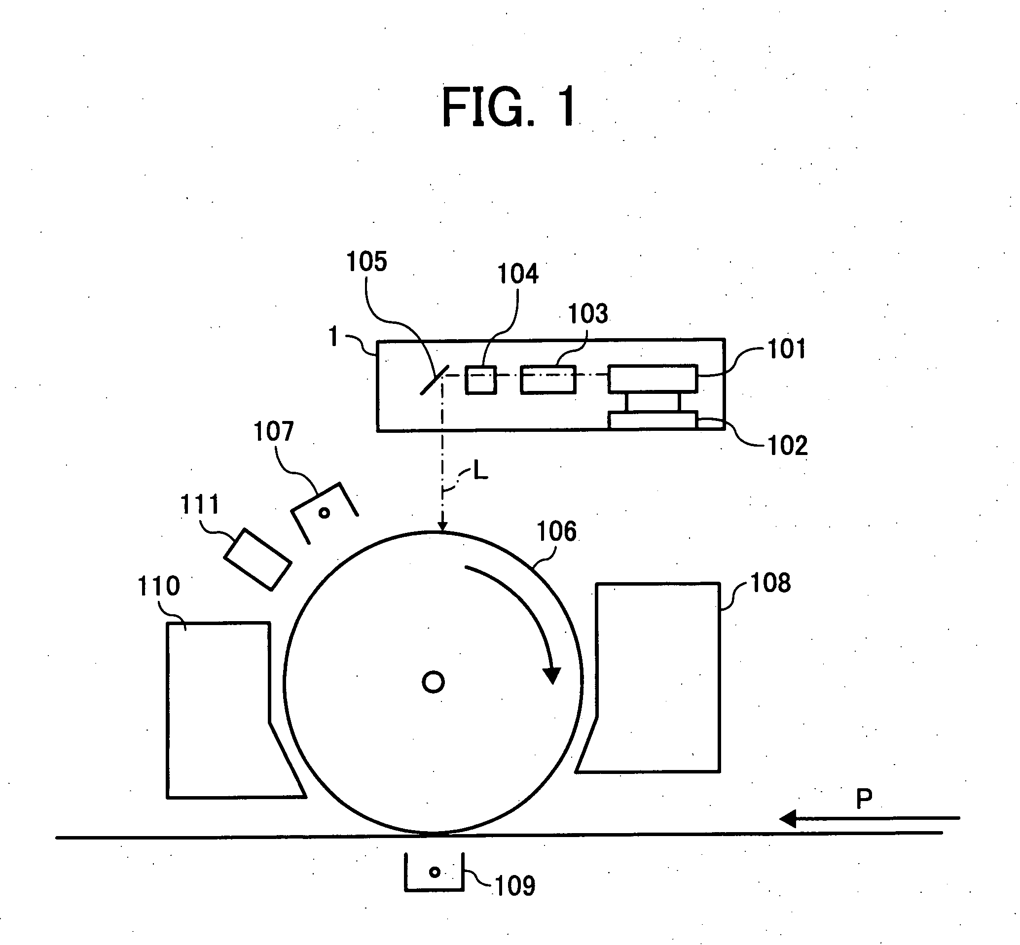
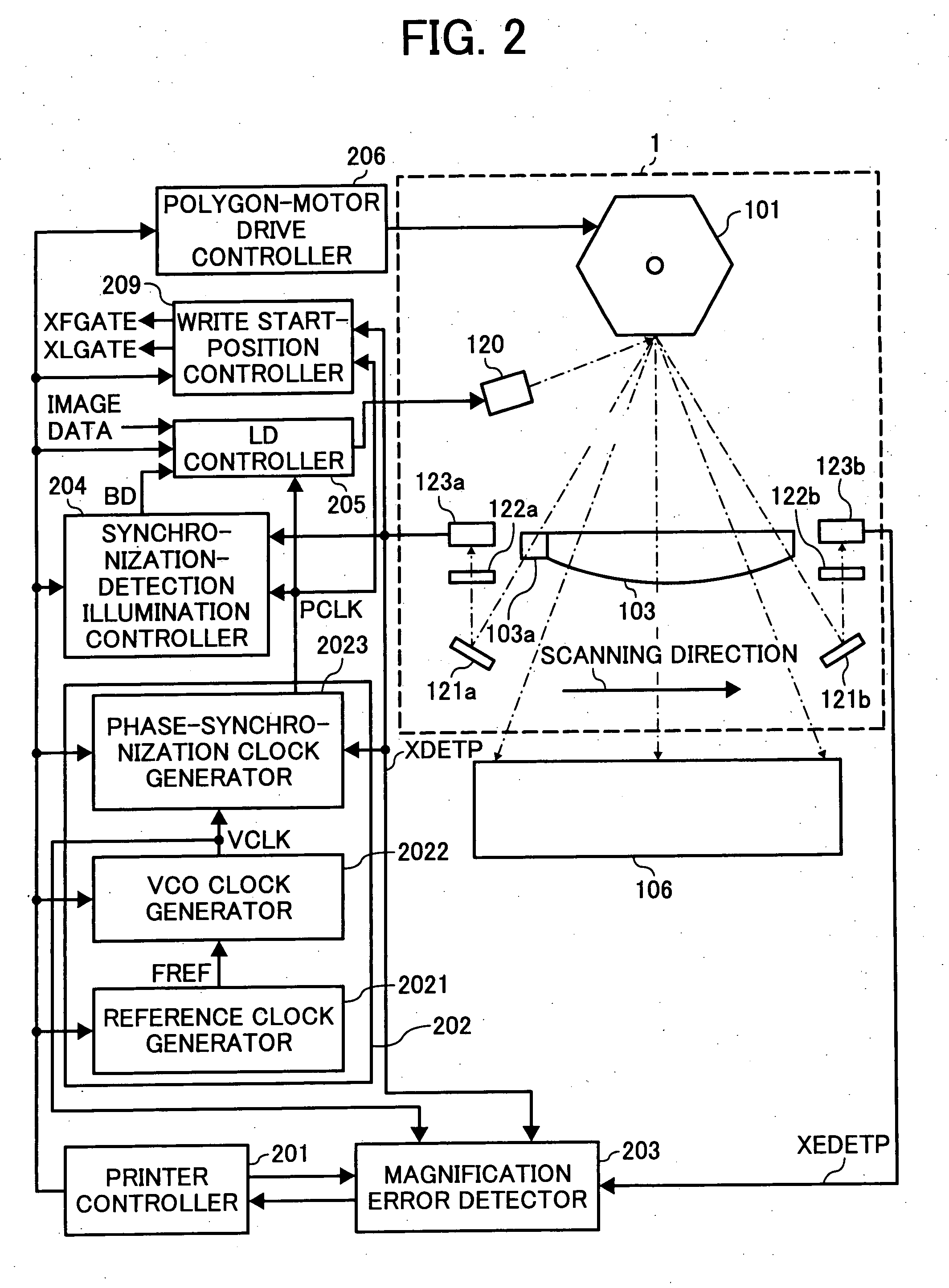
Image forming apparatus and optical scanning apparatus each includes a light source, a deflector, an fθ lens, and first and second light-beam detectors. The light source outputs light beams, and is turned on and is controlled in accordance with image data. The deflector deflects the output light beams in a main-scanning direction. The fθ lens corrects the deflected light beams from constant-angular-velocity scanning to constant-velocity scanning. The first and second light-beam detector detect the deflected light beams at two spots along the main-scanning direction. The first light-beam detector is located at a scanning-start side, and the second light-beam detector is located at a scanning-end side. The light beam that is incident on the first light-beam detector is not transmitted through the fθ lens, and the light beam that is incident on the second light-beam detector is transmitted through the fθ lens.

Description

BACKGROUND OF THE INVENTION [0001] 1. Field of the Invention [0002] The present invention relates to an optical scanning device for performing optical writing in accordance with input image signals and to image forming apparatuses, such as copiers, printers, facsimile apparatuses, and printers (for both color and black-and-white) that include such optical scanning device. [0003] 2. Description of the Related Art [0004] In a known image forming apparatus using light-beams scanning device, light beams are modulated with image data and are deflected at a constant angular velocity in a main-scanning direction by rotation of deflecting means (hereinafter referred to as a “polygon mirror”), the constant angular-velocity deflection is corrected to constant velocity deflection by an fθ lens, and the resulting beams scan on an image holder (hereinafter referred to a “photoreceptor”). However, the known apparatus has a problem in that the image magnification varies from apparatus to apparatus...

Claims


Application Information

Patent Timeline
Patent Type & Authority Applications(United States)
IPC IPC(8): H01J40/14H01J3/14
CPCG02B26/125G02B26/127G03G15/0415H04N1/0402H04N1/0411H04N1/0446H04N2201/04789H04N1/1135H04N2201/0471H04N2201/04729H04N2201/04732H04N2201/04744H04N2201/04772H04N1/053
Inventor MAEDA, KATSUHIKO
Owner RICOH KK
Why Eureka
Try Eureka