
Integrated device having a plurality of chip arrangements and method for producing the same

a technology of integrated devices and chip arrangements, which is applied in the direction of semiconductor devices, semiconductor/solid-state device details, electrical devices, etc., can solve the problems of high cost, high overall height of electronic devices, and increase the height of encapsulation of each die, so as to achieve high integration and reduce manufacturing costs

Inactive Publication Date: 2007-09-13
INFINEON TECH AG
View PDF15 Cites 18 Cited by
  • Summary
  • Abstract
  • Description
  • Claims
  • Application Information

AI Technical Summary

Benefits of technology

[0007] Therefore, one embodiment of the present invention provides an integrated device having a plurality of chip arrangements which can be manufactured with reduced costs and provide a high integration.
[0010] A further embodiment of the present invention provides a method for producing an integrated device having a plurality of chips with a high yield and in a cost-efficient manner, wherein the height of the produced integrated device is reduced compared to a conventional package stack.
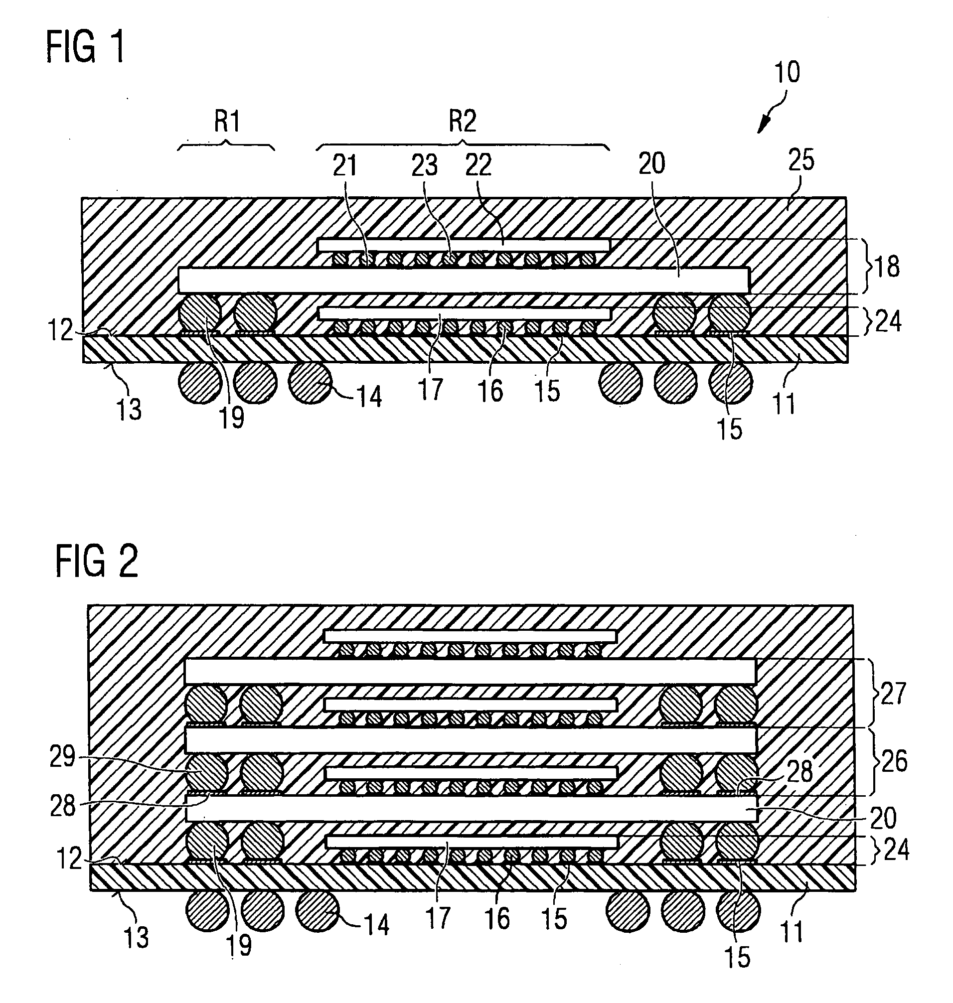
[0012] In the present invention, a chip arrangement is defined as a chip which is provided with a plurality of contact elements for providing external contacts to the chip by placing the contact elements on respective contact pads. In one embodiment, the contact pads are formed as solder bumps, e.g., solder balls, which may be soldered to the respective contact pads. The chip arrangement is non-encapsulated so that the height of the chip arrangement is not unnecessarily increased. On the other hand, the contact element allows for carrying out a functional test of the chip in a facilitated and cost-effective manner prior to the stacking. To protect the chip arrangements from the environmental influences, a common integral mold is arranged around the chip arrangements to encapsulate them.

Problems solved by technology

According to the first proposal above, a stacking of bare dies requires each of the dies to be tested before being stacked and packaged, which is technically expensive and time-consuming and causes high costs.
Regarding the second proposal above, the stacking of packaged devices wherein each packaged device is separately encapsulated with a mold to protect the die therein from the environment, however, has an issue in that the encapsulation of each die increases their heights such that the overall height of the electronic device becomes undesirably high.

Method used


Image

  • Integrated device having a plurality of chip arrangements and method for producing the same
  • Integrated device having a plurality of chip arrangements and method for producing the same
  • Integrated device having a plurality of chip arrangements and method for producing the same

Examples


first embodiment

[0029] As shown in the present invention, the mold 25 is applied on the first surface 12 of the package substrate 11 such that the second surface 13 of the package substrate 11 is not covered with the mold 25 so that the first contact element 14 can be externally connected to apply electrical signals to each of the chips in the integrated device 10.

second embodiment

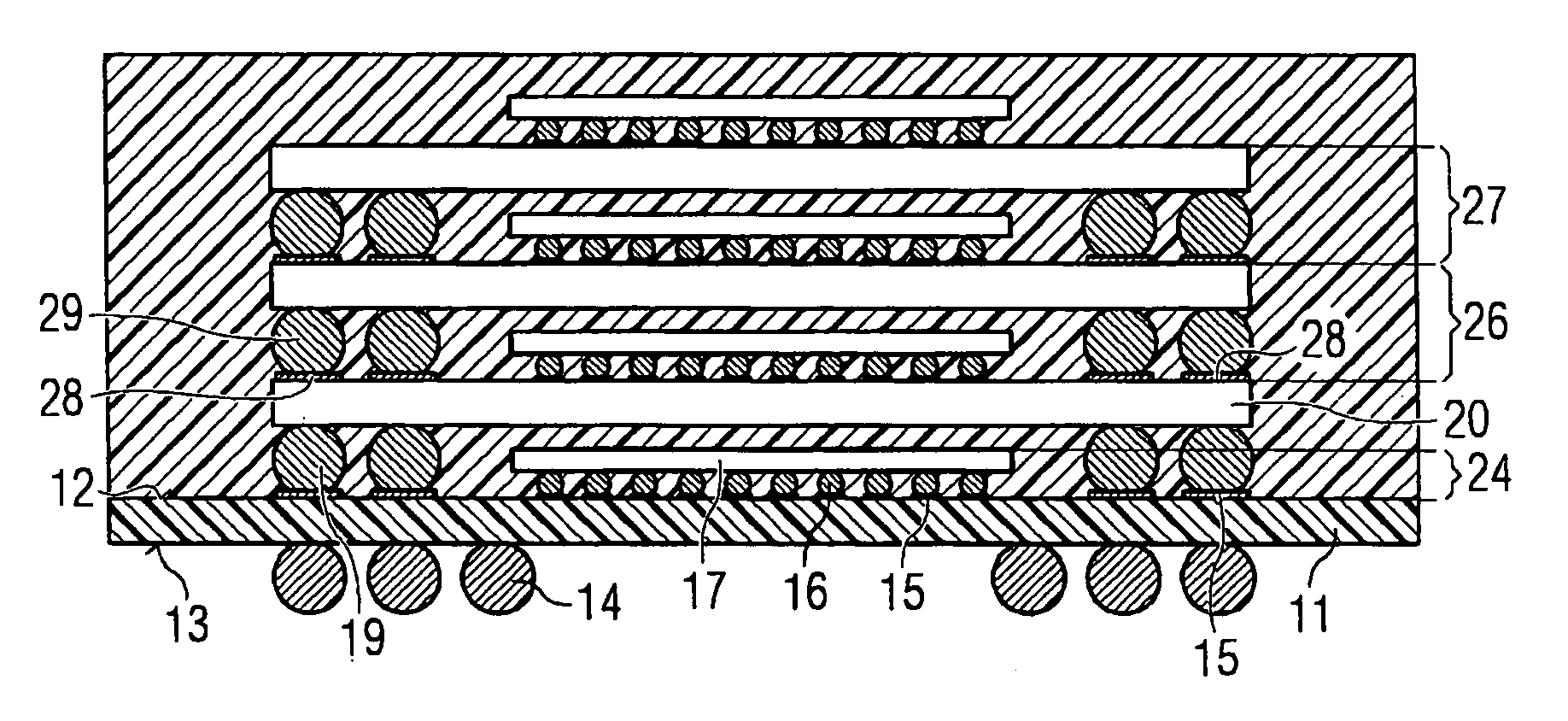
[0030] In FIG. 2, the present invention is shown. Same reference signs indicate elements with the same or similar functionality. The embodiment of FIG. 2 differs from the embodiment of FIG. 1 in that on the second chip arrangement 18, two further, i.e., a third and a fourth, (although other numbers of further chip arrangement are also contemplated) chip arrangements 26, 27 in the form of BGA arrangements are stacked. To provide an electrical connection, third contact pads 28 are provided on the substrate 20 of the second chip arrangement 18 so that the third chip arrangement 26 stacked thereon can be placed so that its fifth contact elements 29 are associated to the third contact pads 28 on the substrate 20. In a similar manner, each of the further chip arrangements can be stacked wherein its respective contact elements contact respective contact pads of one of the respective chip arrangements which is located below with regard to the package substrate 11.

[0031] As already explained...

fourth embodiment

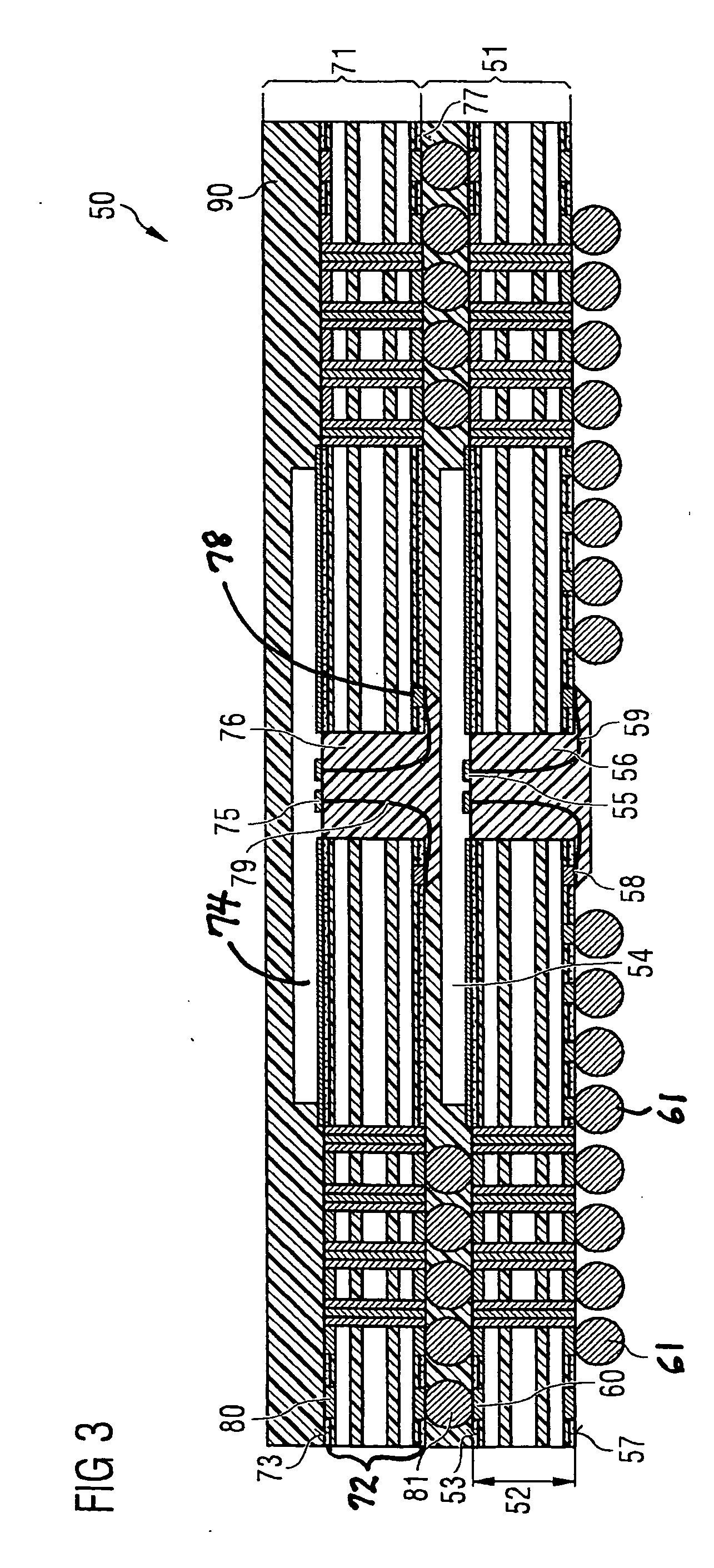
[0035] In FIG. 4, the integrated device 151 according to the present invention is shown. Elements having the same reference signs as the elements of the embodiment of FIG. 3 have the same or similar functionality. The embodiment of FIG. 4 differs from the embodiment of FIG. 3 in that the first substrate 52 is larger in size than the second substrate 172, wherein the second chip arrangement 171 is placed on the first substrate 52 such that the second chip arrangement 171 completely lies within the area defined by the first substrate 52 of the first chip arrangement 51. The common mold 90 which is applied now encapsulates the second chip arrangement 171 and covers the first surface 53 of the first chip arrangement 51.

[0036] For any embodiments, the integrated device can be provided with one or more thermal element which, in the case of FIG. 4, can be provided as a further contact element on the second surface 57 of the first substrate 52 and which reduces the thermal resistance betwee...


PUM


Abstract

The invention provides an integrated device comprising a plurality of non-individually-encapsulated chip arrangements, each of which having a plurality of contact elements for contacting a contact pad, wherein the plurality of chip arrangements are stacked on each other such that the respective contact elements provide electrical connections to the respective chip arrangement, and a common integral mold arranged to encapsulate the plurality of stacked chip arrangements.

Description

CROSS-REFERENCE TO RELATED APPLICATIONS [0001] This application is related to U.S. patent application Ser. No. 11 / 039,293, Attorney Docket No. INFN / 0097 (2004P53356US), entitled SIGNAL REDISTRIBUTION USING BRIDGE LAYER FOR MULTICHIP MODULE, filed Jan. 20, 2005, by Thoai That Le et al., U.S. patent application Ser. No. 11 / 208,362, Attorney Docket No. INFN / 0140, entitled METHOD FOR MCP PACKAGING FOR BALANCED PERFORMANCE, filed Aug. 19, 2005, by Farid Barakat et al., and U.S. patent application Ser. No. 11 / 079,620, Attorney Docket No. INFN / WB0157, entitled METHOD FOR PRODUCING CHIP STACKS AND CHIP STACKS FORMED BY INTEGRATED DEVICES, filed Mar. 14, 2005, by Harald Gross. Each of the aforementioned related patent applications is herein incorporated by reference in its entirety.BACKGROUND OF THE INVENTION [0002] 1. Field of the Invention [0003] The present invention is related to an integrated device having a plurality of chip arrangements, each of which being provided with one or more c...

Claims


Application Information

Patent Timeline
IPC IPC(8): H01L23/02H01L21/00
CPCH01L23/13H01L23/3128H01L2224/73215H01L2224/32225H01L2924/15331H01L2924/15311H01L2924/14H01L2225/06596H01L2225/06589H01L2225/06586H01L2225/06551H01L2225/0652H01L25/0657H01L2224/16225H01L2224/48091H01L2224/4824H01L2225/0651H01L2225/06517H01L2924/00014H01L2924/00
Inventor SUBRAYA, RAJESHFISCHER, HELMUTWENNEMUTH, INGOGOSPODINOVA, MINKATHOMAS, JOCHEN
Owner INFINEON TECH AG
Learn More