

Capacitive humidity sensor
a humidity sensor and capacitance technology, applied in the direction of resistance/reactance/impedence, instruments, measurement devices, etc., can solve the problems of noise generation of initial capacitances of elements, temperature dependence may be generated, and increase manufacturing costs
- Summary
- Abstract
- Description
- Claims
- Application Information
AI Technical Summary
Benefits of technology
Problems solved by technology
Method used
Image

Examples
first embodiment
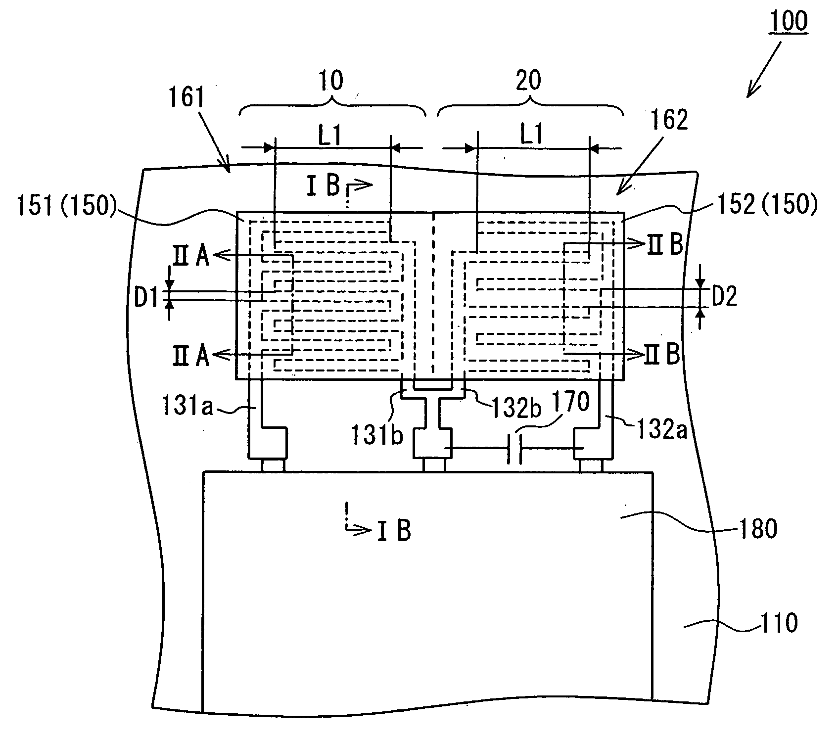
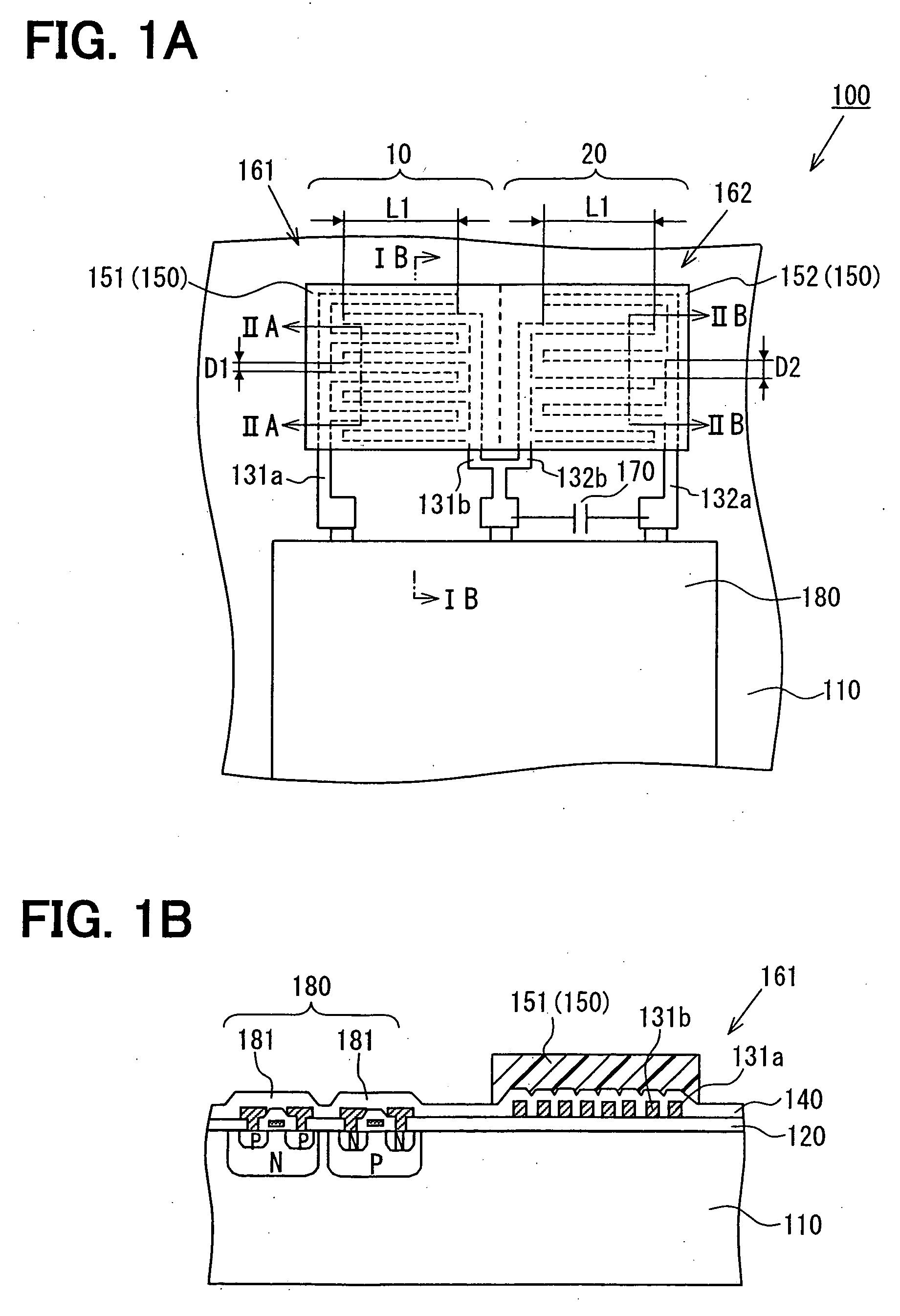
[0024]As shown in FIGS. 1A and 1B, a capacitive humidity sensor 100 includes a semiconductor substrate 110 made of silicon, for example, in a first embodiment. An insulation film 120 made of oxide silicon, for example, is layered on the semiconductor substrate 110, as shown in FIG. 1B. A pair of detecting electrodes 131a, 131b is arranged on the insulation film 120, and the electrodes 131a, 131b face each other with a clearance therebetween.
[0025]A capacitance between the detecting electrodes 131a, 131b varies in accordance with humidity. Each of the detecting electrodes 131a, 131b is shaped into teeth of a comb, as shown in FIG. 1A. Due to this shape, a facing area of the detecting electrodes 131a, 131b can be increased, while an area occupied by the detecting electrodes 131a, 131b can be reduced. Thereby, sensitivity of the sensor 100 can be improved, because a variation of the capacitance can be increased. However, the shape of the detecting electrodes 131a, 131b is not limited t...
second embodiment
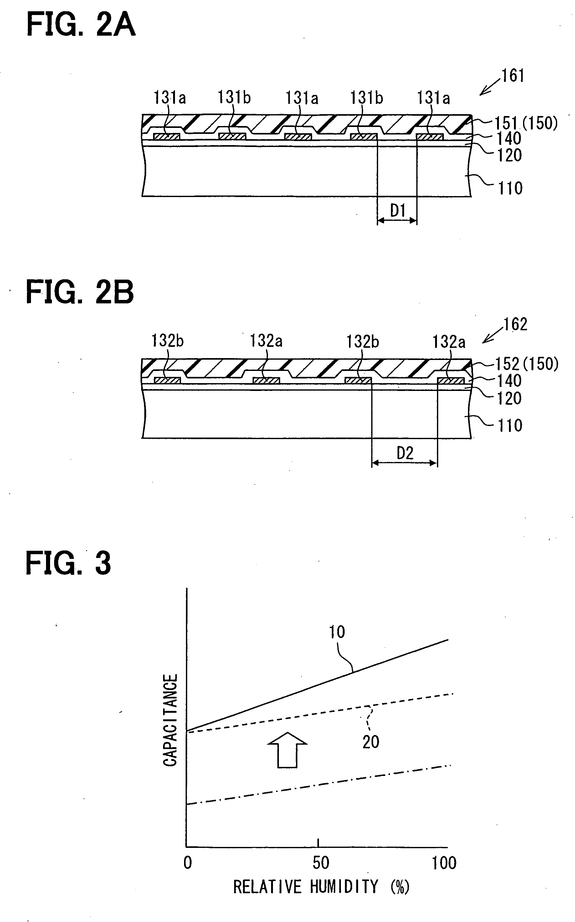
[0042]A first moisture-sensing film 151 and a second moisture-sensing film 152 are made of different materials in a second embodiment, thereby a gradient of a capacitance variation to a humidity variation is made different between a first sensor element 161 and a second sensor element 162. Detecting electrodes 131a, 131b and reference electrodes 132a, 132b have the same construction (pattern) in the second embodiment. The other parts in the second embodiment may be made similar to the first embodiment.
[0043]As shown in FIG. 6, a clearance D5 between the detecting electrodes 131a, 131b is approximately equal to a clearance D5 between the reference electrodes 132a, 132b. A facing dimension L5 between the detecting electrodes 131a, 131b is approximately equal to a facing dimension L5 between the reference electrodes 132a, 132b. The first and second sensor elements 161, 162 have the same number, e.g., eight, of electrodes, respectively. In contrast, the first moisture-sensing film 151 a...
third embodiment
[0048]As shown in FIG. 7B, detecting electrodes 131a, 131b are arranged so as to face each other in a substrate thickness direction through a clearance, and a first moisture-sensing film 151 is disposed in the clearance between the detecting electrodes 131a, 131b in a third embodiment. Similarly, reference electrodes 132a, 132b are arranged so as to face each other in a substrate thickness direction through a clearance, and a second moisture-sensing film 152 is disposed in the clearance between the detecting electrodes 132a, 132b. That is, the electrodes 131a, 131b (132a, 132b) have a parallel plate structure. The other parts in the third embodiment may be made similar to the first and second embodiments.
[0049]As shown in FIGS. 7A and 7B, a bottom electrode 131a is formed on a substrate 110 through an insulation film 120. A top electrode 131b is formed on the bottom electrode 131a through a protection film 140 and a first moisture-sensing film 151. Similarly, a bottom electrode 132a...
PUM
 Abstract
Description
Claims
Application Information