Lens vignetting correction algorithm in digital cameras

a correction algorithm and digital camera technology, applied in the field of digital data processing of pictorial information, can solve the problems of inability to adapt to real-time digital cameras, insufficient recursive approach, and insufficient processing hardwar

Inactive Publication Date: 2007-09-13
ATMEL CORP
View PDF9 Cites 67 Cited by
  • Summary
  • Abstract
  • Description
  • Claims
  • Application Information

AI Technical Summary

Benefits of technology

[0008] The present invention is a lens vignetting correction algorithm implemented in image processing hardware and associated software. The correction applied to the image data is a 4th-order polynomial function in polar form with only the three even-order coefficients being non-zero. This function defines a radially symmetric curve that expresses the relative intensity correction to be applied to each pixel as a function of the radial distance of that pixel from a center. The center of the correction curve may vary with the optical alignment of each camera, or may be assumed to be very close to the center of the image. The variable coefficients, possibly camera-specific, may be found by fitting of the image data directly to the polynomial correction function, for example, by a least-squares fitting technique. The algorithm applies the polynomial correction function to the several pixels of the image using an iterative calculation that eliminates the need for extra hardware, such as multipliers or look-up tables.

Problems solved by technology

This imaging defect causes the image intensity to decrease toward the edges of an image.
It lacks a recursive approach suitable for real-time digital cameras.
Although only one parameter f2 needs to be determined, the correction calculation itself contains trigonometric functions (cos, tan−1), exponentiation (power of 4), logarithms and division, and is therefore quite complex and in need of extensive processor hardware.
Thus, the method involves both a complexity of computation and the need for look-up tables in order to implement the correction with any reasonable degree of efficiency.

Method used


Image

  • Lens vignetting correction algorithm in digital cameras
  • Lens vignetting correction algorithm in digital cameras
  • Lens vignetting correction algorithm in digital cameras

Examples


Embodiment Construction

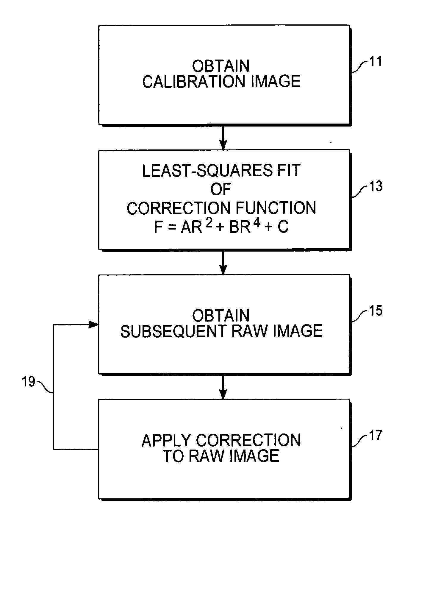
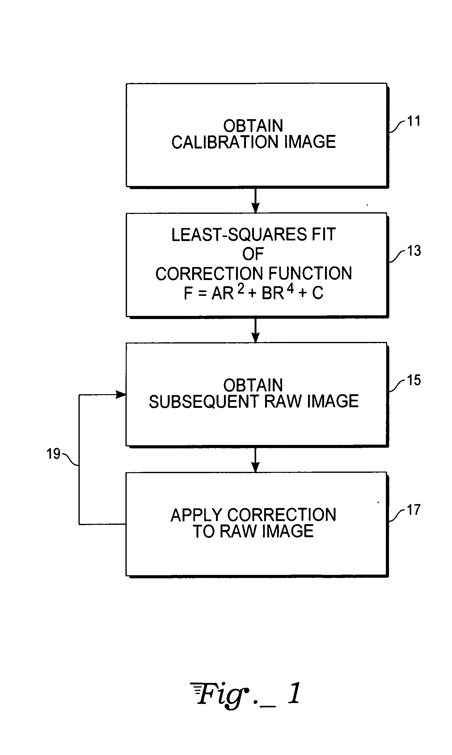
[0010] With reference to FIG. 1, the basic flow of a vignetting correction method in accord with the present invention begins with obtaining a calibration image (step 11) using an imaging system, such as digital still camera, digital video camcorder, or other imaging instrument. The calibration image may be that of a uniformly-lit gray surface. However, due to vignetting, the calibration image will exhibit a falloff in intensity away from the image center.

[0011] Next, a least-squares fit of the correction function (step 13) is performed. Least-squares (or minimum mean square error) is just one possible technique for fitting the parameters to the imaging characteristics of the optical system. Other fitting techniques could also be used to obtain a set of “best” parameters depending on the optimality criterion used.

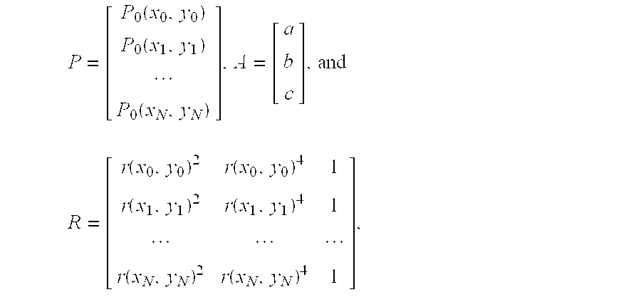
[0012] For the present invention, the lens vignetting correction function is chosen to be a radially symmetric 4th-order polynomial,

F(x,y)=ar2+br4+c,

where (x,y) is the...


PUM


Abstract

A lens vignetting correction method for use in imaging systems such as digital cameras employs a polynomial correction function F=ar2+br4+c, wherein r is a distance to a center of correction. A calibration image is obtained using the imaging system, then the correction function applied to the calibration image is least-squares fit to determine the variable coefficients a, b and c. Subsequent raw images from this imaging system are corrected by applying the correction function thereto on a pixel-by-pixel basis. A recursive technique is used to obtain correction function values for given pixel locations from modification of values for preceding pixel locations.

Description

TECHNICAL FIELD [0001] The present invention relates generally to digital data processing of pictorial information derived from digital still cameras, digital video camcorders and other camera-like image-sensing instruments, and in particular relates to image enhancement by means of transformations for scaling the pixel intensity values of a captured image as a function of pixel position. BACKGROUND ART [0002] Vignetting is an optical phenomenon that occurs in imaging systems wherein the amount of light reaching off-center positions of a sensor (or film) is less than the amount of light reaching the center. This imaging defect causes the image intensity to decrease toward the edges of an image. The amount of vignetting depends upon the geometry of the lens and varies with focal length and f-stop. The effect is more apparent in lenses of lower f-stop (larger aperture), which are used especially in semi-pro / professional still cameras and video camcorders. [0003] A lens vignetting corr...

Claims


Application Information

Patent Timeline
Patent Type & Authority Applications(United States)
IPC IPC(8): H04N9/64G06K9/40
CPCH04N5/3572H04N25/61
Inventor MAHMOUD, HESHAMMARKAS, ANASTASSIOSOLIVIER, DARRYL C.
Owner ATMEL CORP
Why Eureka
Try Eureka