Imaging System

a technology of a system and an imager, applied in the field of imagers, can solve the problems of saturating the maximum temperature before the detector, affecting the operation of the operator, and affecting the scene,

Active Publication Date: 2007-09-13
INFRARED SYST GRP USA INC
View PDF6 Cites 26 Cited by
  • Summary
  • Abstract
  • Description
  • Claims
  • Application Information

AI Technical Summary

Benefits of technology

[0025]Advantageously, said processor means includes integration and timing control means arranged to control the detector means sensitivity levels for each pixel and to switch sequentially between said levels, a plurality of store means arranged to store image data for present and previous images at respective sensitivities, combining means arranged to combine said stored image data into a combined data steam based on said threshold criteria being met, and output means arranged to output said combined data stream to said color adder.

Problems solved by technology

However, the longer the accumulation, the lower the maximum temperature before the detector saturates.
However, in such known systems, an operator is faced with using one or other sensitivity level.
However, the fire in the scene will be saturated and detail within the fire will be lost.
However, low contrast, cooler background detail is lost.
However, when a hot part of the scene is viewed and the camera switches to low sensitivity mode, then details in the cooler parts of the scene may be lost, as indicated in FIG.
Clearly, such loss of information is detrimental.
As will be seen from FIGS. 2 and 3, the disadvantage of the prior art is the loss of detail in low contrast areas of a viewed scene and the interruption of viewing caused by the switching of sensitivity levels.
Additional disadvantages include the potential to confuse a user by the necessity to display different transfer functions between scene temperature and display intensity at different times.

Method used


Image

  • Imaging System
  • Imaging System
  • Imaging System

Examples


Embodiment Construction

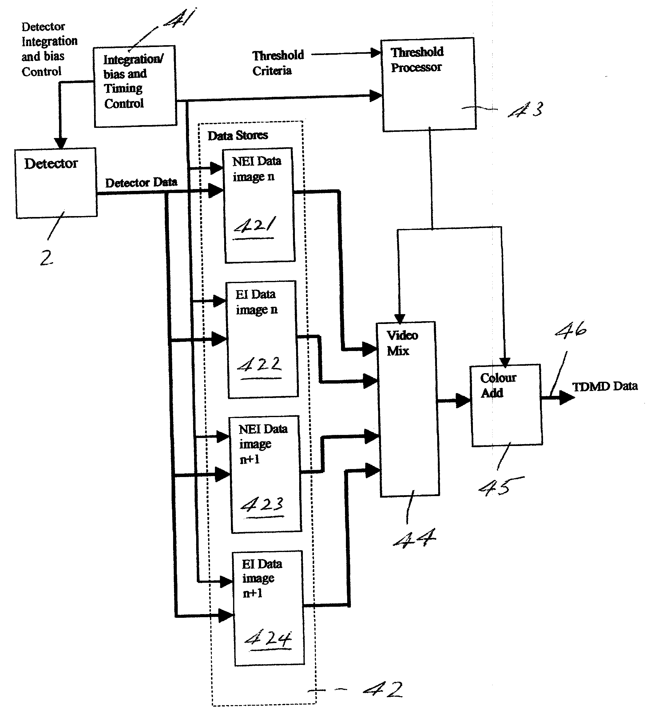
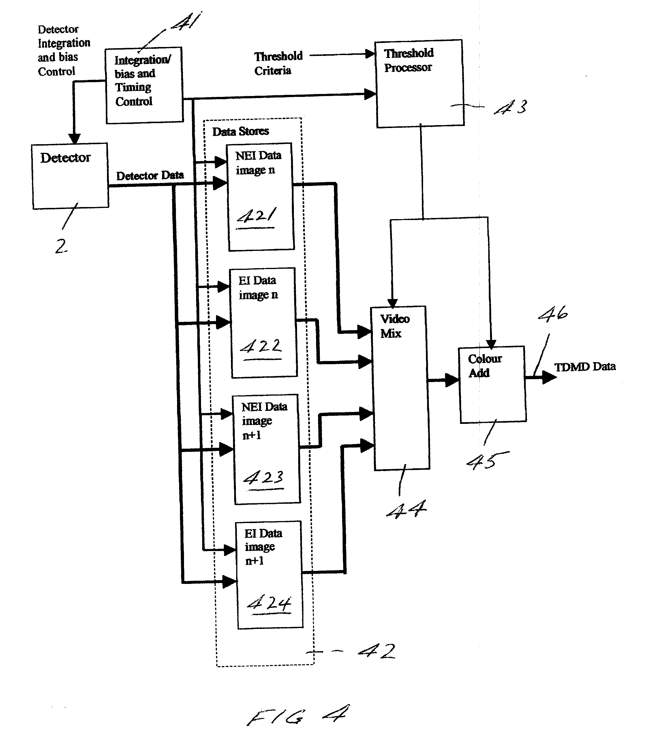
[0045]The imaging system shown in FIG. 4 has a detector 2 controlled by an integration or bias (sensitivity level) and timing control unit 41 and the detector provides output to a data storage block 42 which includes data stores 421-424. The unit 41 also controls a threshold processor 43 having a preset threshold criteria input which may be predetermined or system or operator manually adjustable threshold criteria. The threshold criteria may be, for example, a system predetermined level or be based upon a temperature profile of part of a scene which exceeds a predetermined threshold value and the unit 41 also controls reading in of data to the data storage block 42 and the output of data from the data storage block is, preferably, clocked to a combiner 44 which effectively acts as a multiplexer for signals from each of the stores 421-444. The combiner 44 receives threshold signals from threshold processor 43 and provides output to a color adder 45 where gray scale images derived fro...


PUM


Abstract

An imaging system, particularly a thermal imager, has a detector operating in at least two sensitivity modes. The detector is read on a pixel-by-pixel basis in each of at least two modes and output therefrom is substantially simultaneously displayed so that a wide range of thermal sensitivities are simultaneously displayed.
The detector is, preferably, read out at maximum and minimum sensitivity levels at least half the field rate and, advantageously, at the field rate of a display. In a preferred embodiment, color is added to the normally provided gray scale output from the detector ranging from black for the coolest object through white and yellow to red for the hottest object.

Description

BACKGROUND OF THE INVENTION[0001]1. Field of the Invention[0002]This invention relates to an imaging system and particularly, although not exclusively, to a thermal imaging camera.[0003]2. Description of the Related Art[0004]Imaging systems are known where radiant energy which may be visible light, or infrared, or in the X-ray spectrum, for example, is converted into electrical signals. The term “electrical signals” used herein is meant in its broadest aspect to include electromagnetic and opto-electric signals. Such energy also includes thermal energy used for viewing scenes where extreme temperature differences are evident, for example in fire fighting, where thermal energy is converted by a detector into electrical signals for viewing by an operator. Although this invention is intended principally in thermal imaging situations, the invention is applicable to imaging systems where a compromise is found between dynamic range and low contrast sensitivity.[0005]FIG. 1 shows in block ...

Claims


Application Information

Patent Timeline
Patent Type & Authority Applications(United States)
IPC IPC(8): H04N5/222
CPCG01J5/22H01L27/14601H04N5/33H04N5/2355H04N5/235H04N23/70H04N23/741H01L27/146H04N23/71H04N25/00
Inventor HUMPOLETZ, CHARLES JAMES PETERWILLIS, MARTIN CHARLES
Owner INFRARED SYST GRP USA INC
Why Eureka
Try Eureka