Optical defect inspection apparatus

a defect inspection and optical technology, applied in the direction of optically investigating flaws/contamination, semiconductor/solid-state device testing/measurement, instruments, etc., can solve the problems of deteriorating the reproducibility of the inspection apparatus, difficult to practice the change of the laser illuminated point on the plane mirror to avoid frequent replacement, and the frequency of part replacement can be reduced. , the effect of dispensed alignment of the optical axis of the reflecting mirror

Inactive Publication Date: 2007-09-13
HITACHI HIGH-TECH CORP
View PDF3 Cites 23 Cited by
  • Summary
  • Abstract
  • Description
  • Claims
  • Application Information

AI Technical Summary

Benefits of technology

[0033] According to the one feature of the present invention, since the reflecting mirror is provided with the translation mechanism and the rotation mechanism both causing no displacements of the optical axis, frequency of part replacement can be reduced and alignment of the optical axis of the reflecting mirror can be dispensed with.

Problems solved by technology

However, replacing the plane mirror whenever its reflection is reduced causes a problem in point of cost efficiency.
Also, changing the laser illuminated point on the plane mirror to avoid frequent replacement is not easy to practice in the known apparatus.
The generation of dust causes deposition of foreign matters on the inspected object during transport and inspection thereof, and deteriorates reproducibility of the inspection apparatus.

Method used


Image

  • Optical defect inspection apparatus
  • Optical defect inspection apparatus
  • Optical defect inspection apparatus

Examples


first embodiment

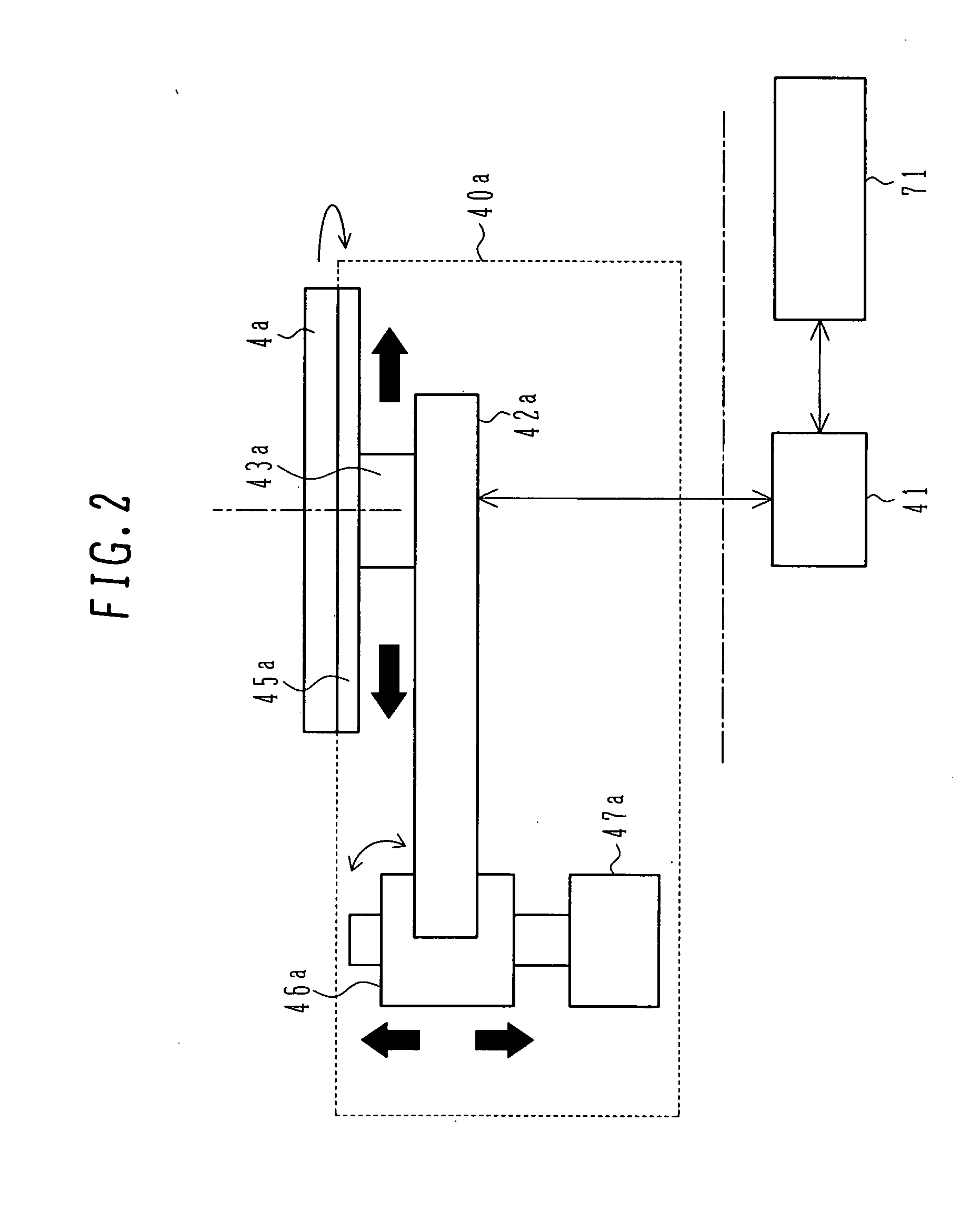
[0048] A first embodiment of the present invention will be first described in detail below with reference to the drawings. A defect inspection apparatus of the first embodiment is intended to suppress variations of conditions, such as a reduction of light quantity (intensity) caused by deterioration of a plane mirror (reflecting mirror), with the provision of a translation mechanism and / or a rotation mechanism, which does not displace an optical axis of the plane mirror, in an optical system.

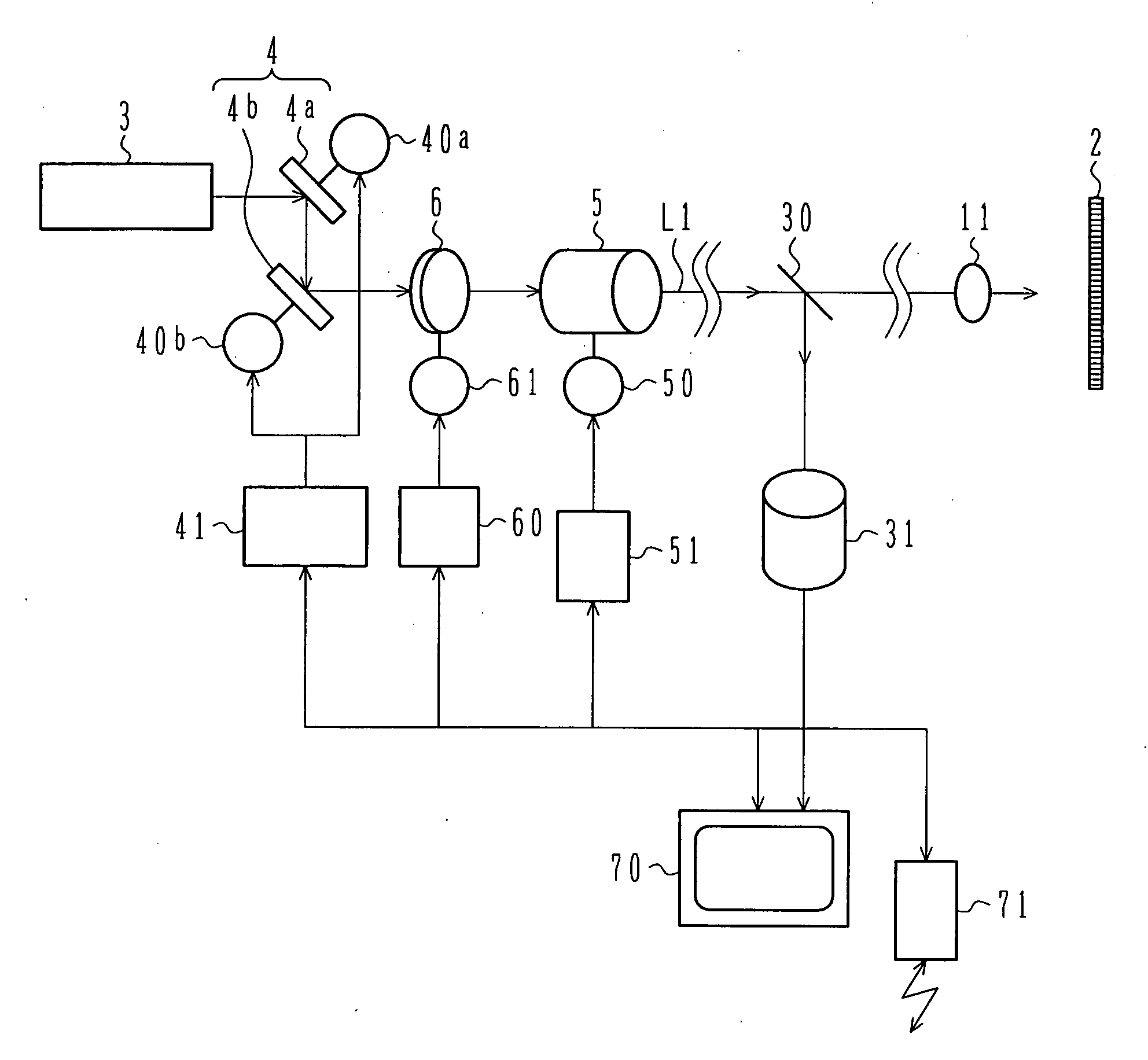
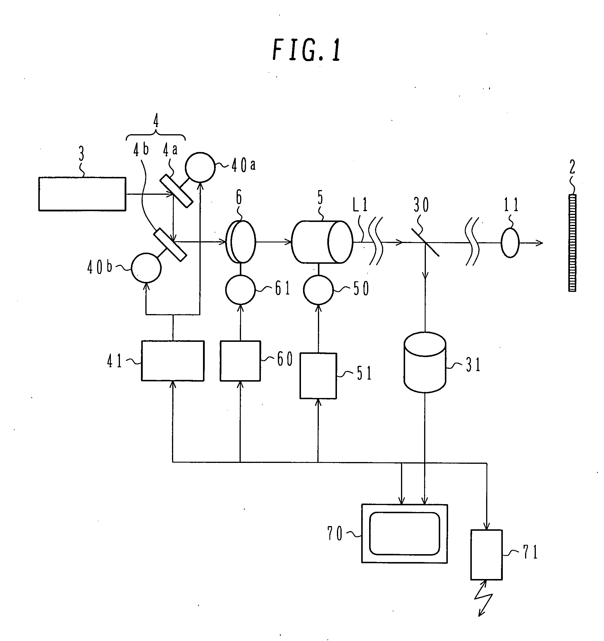
[0049]FIG. 1 schematically shows the construction of an illumination optical system according to the first embodiment of the present invention. The illumination optical system primarily comprises a laser source 3 for emitting an illumination light, e.g., a visible or ultraviolet laser beam, a beam deflection mechanism 4 made up of a plurality of pane mirrors, such as a first plane mirror (reflecting mirror) 4a and a second plane mirror (reflecting mirror) 4b, for deflecting the direction of adv...

second embodiment

[0082] A second embodiment of the present invention will be described in detail below with reference to the drawings. This second embodiment represents the case where the present invention is applied to a surface inspection apparatus. The surface inspection apparatus has the functions of inspecting not only the front surface of an object to be inspected, but also the rear surface thereof. The surface inspection apparatus includes the plane mirror moving mechanisms, the light quantity measuring means, the control means for them, and the diagnosis condition setting means, which are all described above in connection with the first embodiment, but an optical system in the second embodiment differs from that in the first embodiment to some extent.

[0083]FIG. 6 schematically shows the construction of the surface inspection apparatus of the second embodiment. The surface inspection apparatus comprises one or more load ports 150 which also serve to support an inspected object (wafer) 2, a c...


PUM

PropertyMeasurementUnit
angleaaaaaaaaaa
angleaaaaaaaaaa
optical defect inspectionaaaaaaaaaa

Abstract

A laser beam oscillated from a laser source is folded in its path by first and second plane mirrors and enters a beam expander. The surface of each plane mirror is deteriorated with illumination by the laser beam and the reflectance is reduced. To avoid a light quantity of the laser beam entering the beam expander from being reduced below a reference value, when the laser beam is illuminated over a certain time, a position on each of the first and second plane mirrors at which the laser beam is illuminated is changed by a structure for rotating and/or translating a reflecting surface of each plane mirror on a plane, which includes the plane mirror, while an optical axis is kept same. The useful life of each plane mirror can be prolonged without displacing the optical axis itself by overcoming the problem that when the laser beam is employed as the light source and a thin beam with a high illumination density is illuminated to the same position on each of the first and second plane mirrors for a long time, the surface of the plane mirror is deteriorated, the reflectance is reduced, and the light quantity cannot be held at a required level.

Description

BACKGROUND OF THE INVENTION [0001] 1. Field of the Invention [0002] The present invention relates to an apparatus and a method for inspecting an object to be inspected (i.e., an inspection target). More particularly, the present invention is adapted for an optical defect inspection apparatus and method for inspecting foreign matters, defects, etc. on inspected objects in manufacturing processes of, e.g., semiconductor devices, flat panel displays, magnetic disks, and masks. [0003] 2. Description of the Related Art [0004] The capability of detecting finer defects is demanded in an optical defect inspection apparatus for illuminating a light to an object to be inspected, such as a semiconductor device and a flat panel display, and measuring the light reflected or scattered from the object. To meet such a demand, using a light source with higher luminance is required and a laser beam is mainly used as the light source. One known inspection apparatus using the laser beam is disclosed in...

Claims


Application Information

Patent Timeline
Patent Type & Authority Applications(United States)
IPC IPC(8): G01N21/88
CPCG01N21/94G01N21/9501H01L22/12G01N2021/95676G01N2021/9513
Inventor AIZAWA, NORIYUKIKAWAKAMI, HIROYUKIZAMA, KAZUHIROIIJIMA, YUUICHIROTAKAHASHI, KAZUOMIYAZAKI, YUSUKEHACHIYA, MASAYUKIASAMI, KOICHITANAKA, SHINGO
Owner HITACHI HIGH-TECH CORP
Why Eureka
Try Eureka