Lens protecting apparatus for cellular phone camera

a technology for protecting apparatus and cellular phone cameras, applied in camera filters, printers, instruments, etc., can solve the problems of difficult miniaturization of cellular phones, not strong resistance to outside physical impact, scratching of lenses, etc., and achieve the effect of reducing the volume and weight of cellular phones

Inactive Publication Date: 2007-09-13
SAMSUNG ELECTRO MECHANICS CO LTD
View PDF10 Cites 15 Cited by
  • Summary
  • Abstract
  • Description
  • Claims
  • Application Information

AI Technical Summary

Benefits of technology

[0013]Accordingly, the present invention has been made keeping in mind the above problems occurring in the prior art, and an object of the present invention is to provide a lens protecting apparatus for a cellular phone camera which automatically covers and uncovers the lens of the camera using electromagnetic force, thus reducing the volume and weight of the cellular phone.

Problems solved by technology

However, because the lens of the camera of such a cellular phone is usually exposed outside, there are problems in that the lens is scratched by dust or foreign substances and is not strongly resistant to outside physical impact.
However, in the conventional lens protecting apparatus 10, because a device, such as a motor, which is relatively large and heavy, is used as the drive source 40, it is difficult to miniaturize the cellular phone, and the weight of the cellular phone is increased.

Method used


Image

  • Lens protecting apparatus for cellular phone camera
  • Lens protecting apparatus for cellular phone camera
  • Lens protecting apparatus for cellular phone camera

Examples


first embodiment

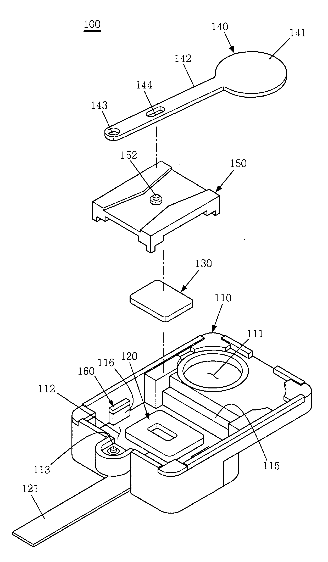
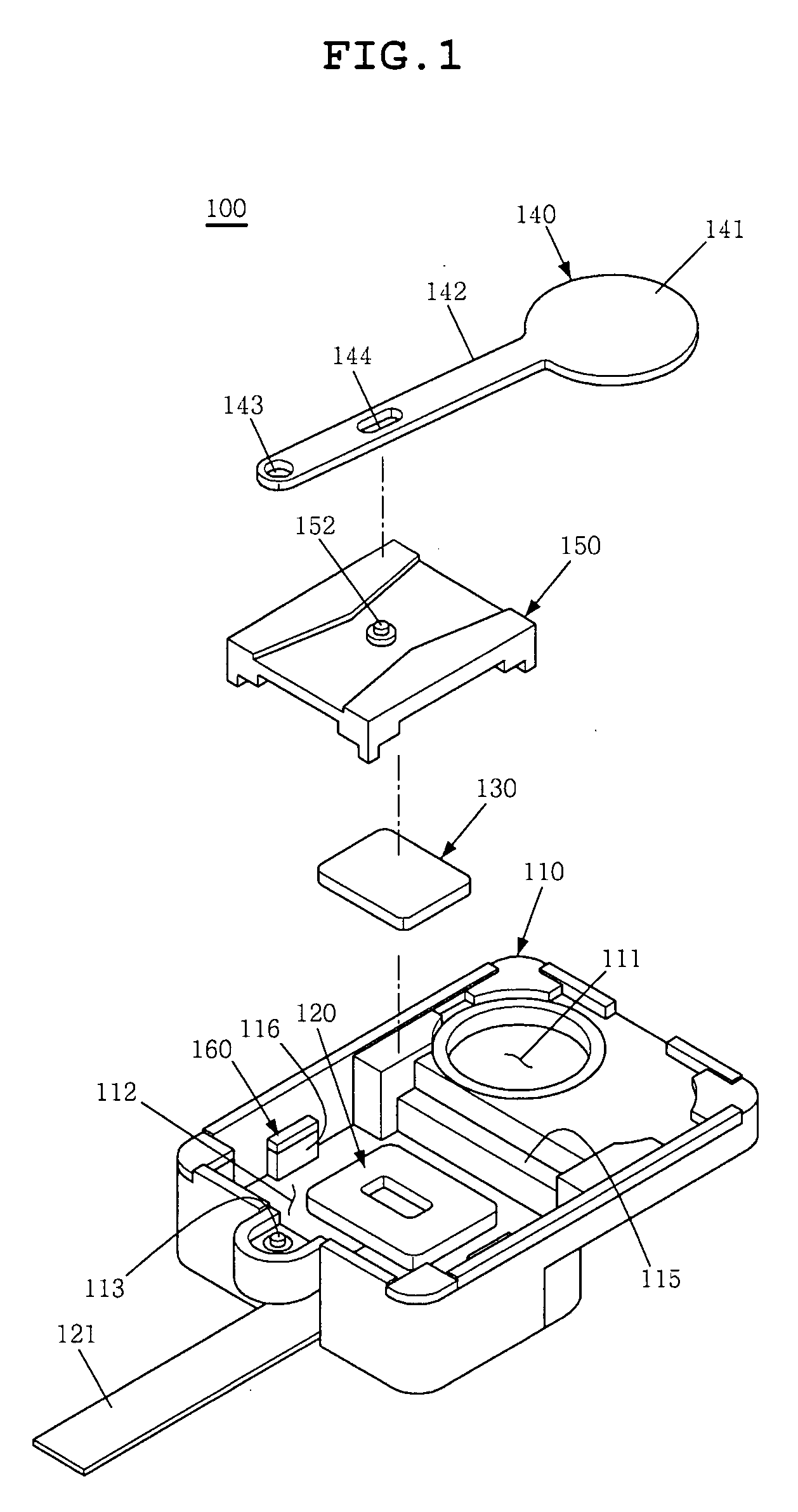
[0034]As shown in FIGS. 1 and 2, the lens protecting apparatus 100 for a cellular phone camera according to the present invention includes a base 110, a coil 120, a magnet 130, a lens cover 140, a mounting member 150 and holding members 160.

[0035]The base 110 is a part to which elements of the lens protecting apparatus 100 are mounted. The base 110 has an opening 111, through which the lens of the camera, which is not shown in the drawings, is exposed outside, and a coupling part 112, to which the coil 120 is mounted.

[0036]The opening 111 is formed in the base 110 at a position displaced from the center of the base 110 towards the perimeter thereof.

[0037]The coupling part 112 is stepped relative to the part in which the opening 111 is formed, such that the coil 120 is disposed at a position lower than the opening 111. The coupling part 112 has a support shaft 113, which rotatably supports the lens cover 140, a seating part 115, on which the mounting member 150 is seated, and support...

second embodiment

[0062]As shown in FIGS. 4 and 5, the lens protecting apparatus 200 according to the present invention includes a base 210, a coil 220, a magnet 230, a lens cover 240, a mounting member 250 and holding members 260.

[0063]Explanation of parts of the general construction of the second embodiment that are similar to corresponding parts in the first embodiment is deemed unnecessary.

[0064]The base 210 is the part to which elements of the lens protecting apparatus 200 are mounted. The base 210 has an opening 211, through which a lens of the camera, which is not shown in the drawings, is exposed outside, and a support shaft 213, which rotatably supports the lens cover 240, a coupling shaft 214, which rotatably supports the mounting member 250, and a coupling part 212, to which the coil 220 is mounted.

[0065]The support shaft 213 is provided between the opening 211 and the coupling part 212, and is disposed at a height equal to the position of the opening 211 such that the lens cover 240 is ma...


PUM


Abstract

Disclosed herein is a lens protecting apparatus for a cellular phone camera. The lens protecting apparatus of the present invention includes a base, which has an opening, through which a lens of the camera is exposed, a coil, which is mounted to the base and is supplied with current, a lens cover, which is rotatably mounted to the base to open or close the opening, and a magnet, which is mounted to the lens cover to form a magnetic field around the coil. The magnet is moved by force generated by the current and the magnetic field, and the lens cover opens or closes the opening using the magnet, to thus move it.

Description

CROSS REFERENCE TO RELATED APPLICATION[0001]This application claims the benefit of Korean Patent Application No. 2006-0022640, filed Mar. 10, 2006, entitled “Lens protecting apparatus for a camera of the cellular phone”, which is hereby incorporated by reference in its entirety into this application.BACKGROUND OF THE INVENTION[0002]1. Field of the Invention[0003]The present invention relates generally to apparatuses for protective lenses for cellular phone cameras and, more particularly, to a lens protecting apparatus for a cellular phone camera which automatically covers and uncovers a lens of the camera, which is exposed outside, thus protecting the lens.[0004]2. Description of the Related Art[0005]As well known to those skilled in the art, a cellular phone is an apparatus which is portable by a user and makes it possible for the user to communicate with counterparts. Recently, to meet the needs of users, cellular phones that have functions of taking, transmitting and receiving pi...

Claims


Application Information

Patent Timeline
Patent Type & Authority Applications(United States)
IPC IPC(8): G03B17/00G03B11/04H04N5/225
CPCG03B11/04H04N5/2254G03B29/00G03B11/043A61J9/00
Inventor KIM, HYO YOUNGKIM, SEUNG BUMKIM, DAE YOUNGMA, SEOG JIN
Owner SAMSUNG ELECTRO MECHANICS CO LTD
Why Eureka
Try Eureka