Toner cartridge, and shutter structure for the same

a technology of toner cartridge and shutter structure, which is applied in the field of toner cartridges, can solve the problems of toner leakage from the toner outlet, and the toner contained in the toner cartridge to be unusabl

Inactive Publication Date: 2007-09-13
KYOCERA DOCUMENT SOLUTIONS INC
View PDF2 Cites 62 Cited by
  • Summary
  • Abstract
  • Description
  • Claims
  • Application Information

AI Technical Summary

Benefits of technology

[0011] A toner cartridge according to a first aspect of the present invention is removably attached to an image forming device. The toner cartridge comprises a container main body, a shutter mechanism, a lever, a lever locking mechanism, a lock releasing mechanism and a prevention mechanism. The container main body contains toner and has a toner outlet. The shutter mechanism opens or closes the toner outlet of the container main body. The lever is rotatably supported by the container main body for operating the shutter mechanism. The lever locking mechanism locks the lever to be inoperative while the toner outlet is closed by the shutter mechanism. The lock releasing mechanism unlocks the lever which is locked by the lever locking mechanism in conjunction with installation of the container main body to the image forming device. The prevention mechanism prevents the container main body from being taken out of the image forming device while the container main body is installed in the image forming device and the lever operates the shutter mechanism to open the toner outlet.
[0012] When the toner cartridge is not installed in the image forming device, the toner outlet is closed by the shutter mechanism. When the toner outlet is closed, the lever operating the shutter mechanism is locked. When the toner cartridge is installed into the image forming device, the lever is unlocked in conjunction with the installation. Accordingly, in this state, the lever can be manipulated to operate the shutter mechanism to open the toner outlet. As a result, the toner inside the container main body is supplied to the image forming device. In addition, while the container main body is installed in the image forming device and the shutter mechanism is operated by the lever to open the toner outlet, the container main body is prevented from being taken out of the image forming device.
[0013] In this case, since the lever for operating the shutter mechanism is locked while the toner cartridge is not installed in the image forming device and the toner outlet is closed, the lever can not move to open the toner outlet so that the leakage of toner is prevented. In addition, since the lever is unlocked in conjunction with installation of the toner cartridge into the image forming device, it is possible smoothly open the toner outlet. Furthermore, since the container main body is prevented from being taken out of the image forming device while the toner outlet is opened, the container main body cannot be taken out with the toner outlet open, thereby preventing the leakage of toner.

Problems solved by technology

It is undesirable for the toner contained in the toner cartridge to leak before the toner cartridge is installed into the image forming device main body, after the toner cartridge is released from the device main body, or during the operation of installation or removal.
However, while the toner cartridge is installed in the image forming device main body and the toner outlet is in the opened state, operating errors such as taking the toner cartridge out of the image forming device main body could cause the toner to leak from the toner outlet.

Method used


Image

  • Toner cartridge, and shutter structure for the same
  • Toner cartridge, and shutter structure for the same
  • Toner cartridge, and shutter structure for the same

Examples


first embodiment

Overall Structure

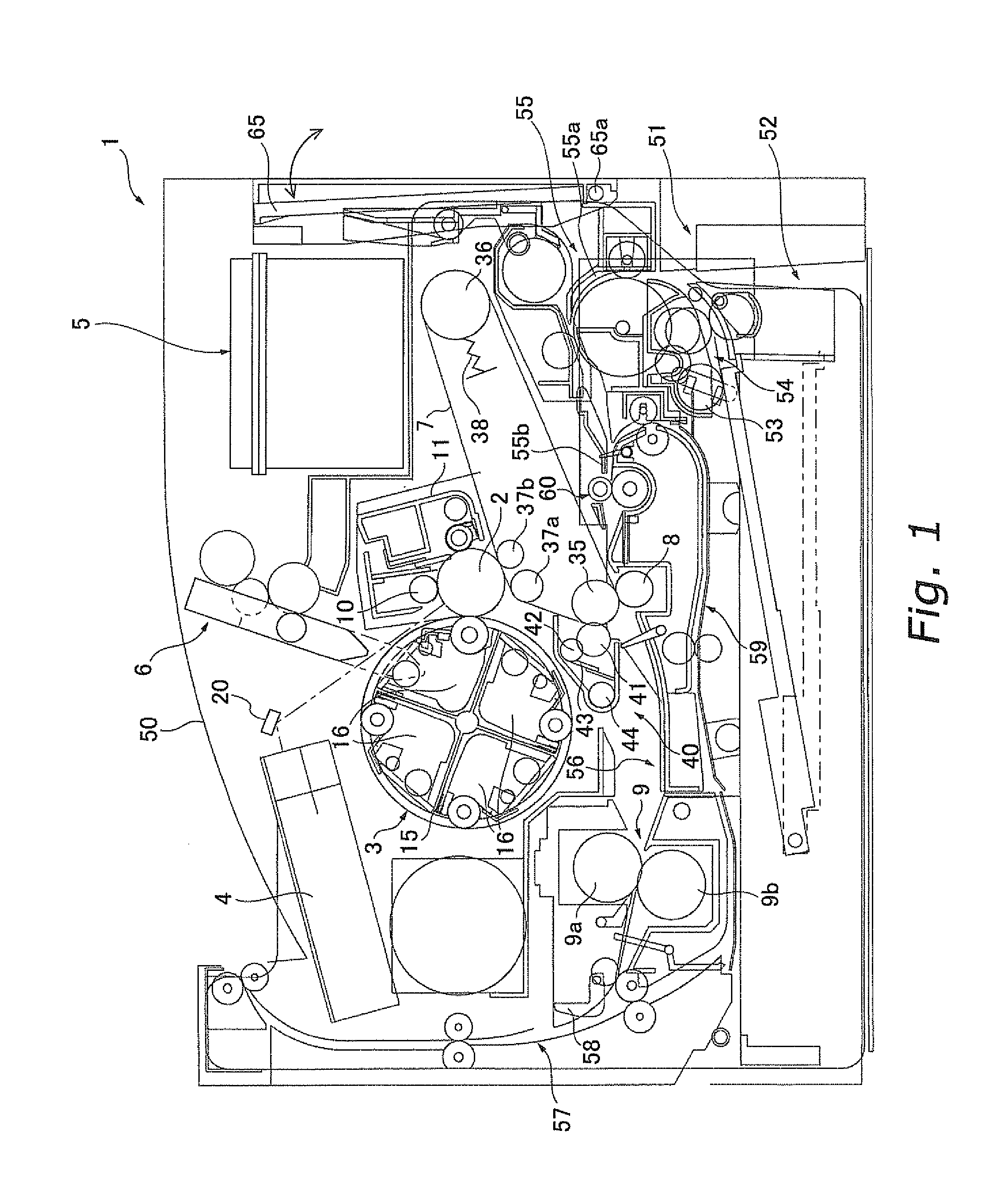
[0052]FIG. 1 shows a color printer 1 as an image forming device employing a toner cartridge according to an embodiment of the present invention. FIG. 1 shows the locations of each of the components in the color printer 1, with some of the details of each of the components omitted.

[0053] The color printer 1 is connected to a device, such as a computer for example, not shown in the figure, and is capable of printing a color image onto a sheet based on image data received from the computer. Note that the right hand side of this color printer 1 shown in FIG. 1 is where an operator operates the color printer 1. The right hand side is hereinafter referred to as the “front side”, where the left hand side thereof is hereinafter referred to as the “rear side”.

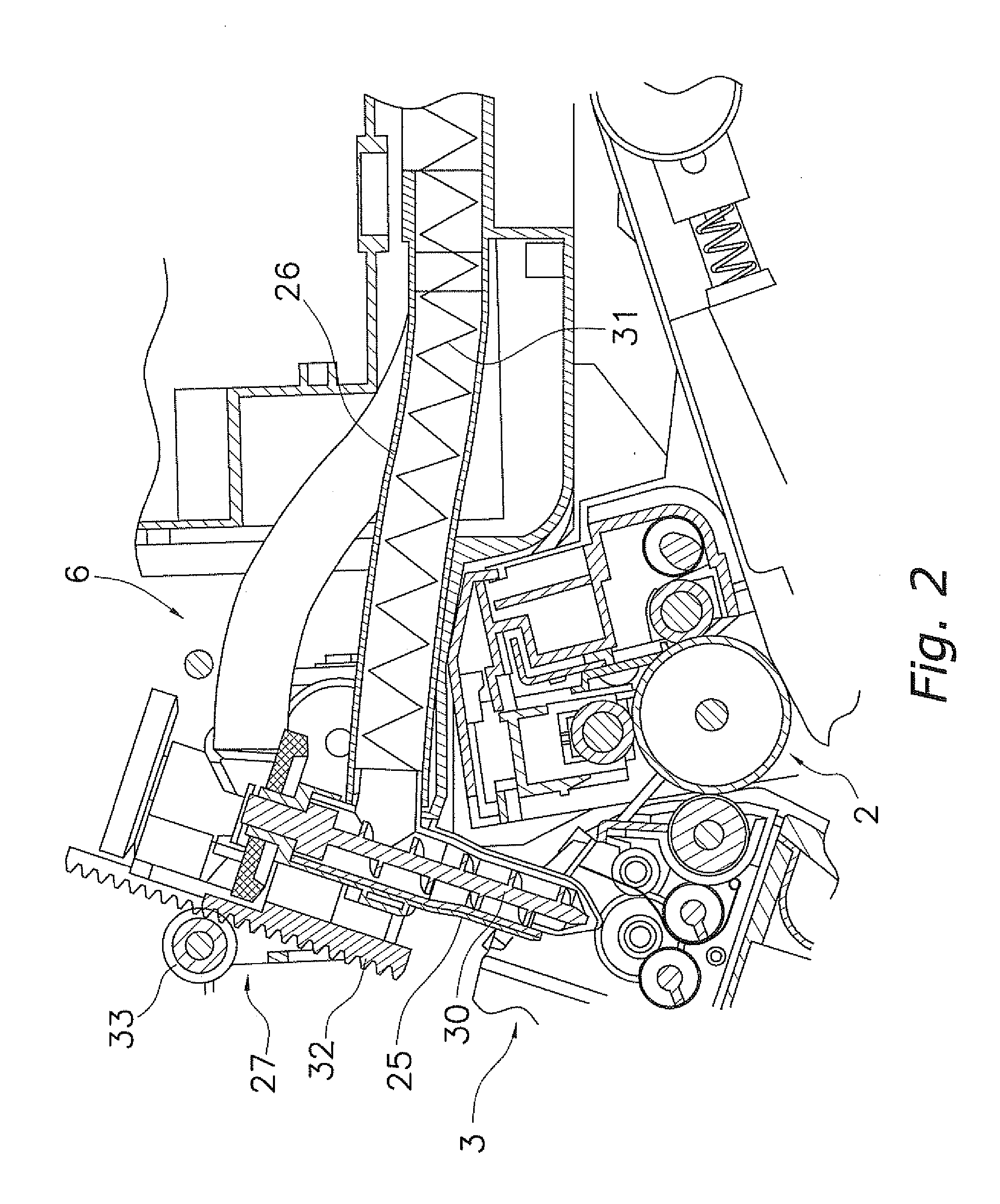
[0054] The color printer 1 includes a photosensitive drum 2, a rotary developing unit 3, a laser unit 4 as an exposure unit, a toner storage unit 5, a toner supply unit 6, an intermediate transfer belt 7, a secondar...

second embodiment

[0097] A second embodiment of the present invention is shown in FIGS. 10A, 10B, and 11. In the second embodiment, since only the toner cartridge is different from the first embodiment, and the other structures are the same, a description will be made only on the toner cartridge hereinafter.

Toner Cartridge

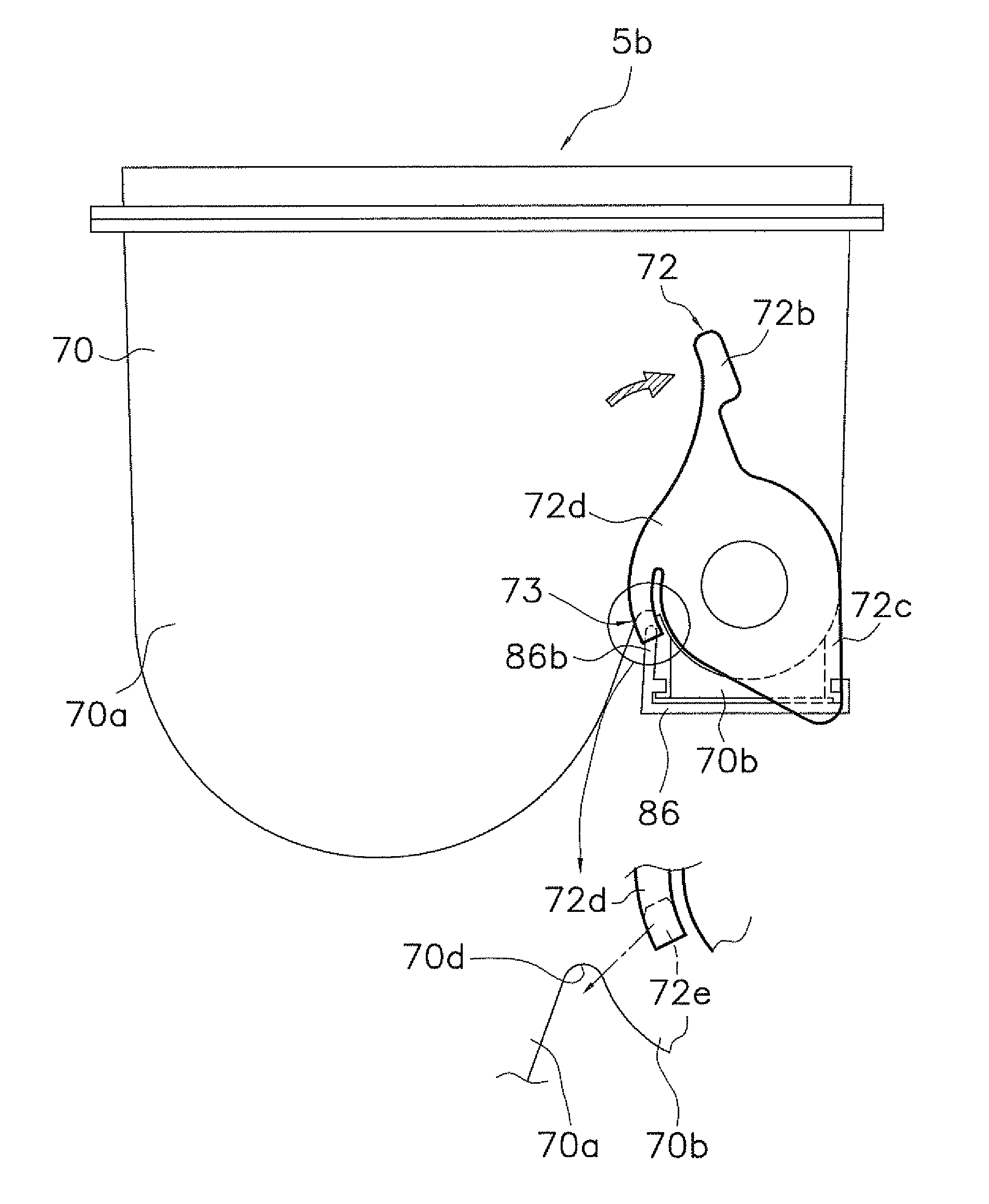
[0098] All of the toner cartridges have the same fundamental structure. In this embodiment, the toner cartridge 105b that contains black toner will be described in detail referring to FIGS. 10A, 10B, and 11.

[0099] The toner cartridge 105b can be installed in or removed from the main body of the color printer 1 with a sliding movement in nearly a horizontal direction. The toner cartridge 105b is composed of a container main body 170 to contain toner inside, a shutter mechanism, a lever 172 to operate the shutter mechanism, a lever locking mechanism 173 for locking the lever 172 to be inoperative, a lock releasing mechanism 174 to release the lock on the lever 172 by the lever loc...


PUM


Abstract

A toner cartridge includes a container main body includes a toner outlet, a shutter mechanism for opening and closing the toner outlet, a lever for operating the shutter mechanism, a lever locking mechanism, a lock releasing mechanism, and a prevention mechanism. The lever locking mechanism locks the lever so as to be inoperative while the toner outlet is closed. The lock releasing mechanism unlocks the lever locked by the lever locking mechanism in conjunction with installment of the container main body into the image forming device. The prevention mechanism prevents the container main body from being taken out of the image forming device while the container main body is installed in the image forming device, and the lever operates to open the toner outlet.

Description

CROSS-REFERENCE TO RELATED APPLICATIONS [0001] This application claims priorities to Japanese Patent Application Nos. 2005-099181 and 2006-014961. The entire disclosure of Japanese Patent Application Nos. 2005-099181 and 2006-014961 are hereby incorporated herein by reference. BACKGROUND OF THE INVENTION [0002] 1. Field of the Invention [0003] The present invention relates to a toner cartridge, and more particularly relates to a toner cartridge that is releasably installed in an image forming device. Furthermore, the present invention relates to a shutter structure of the toner cartridge, particularly to a shutter structure for opening and closing a toner outlet of a toner cartridge that is removably installed in an image forming device. [0004] 2. Background Information [0005] An image forming device such as a copying machine includes a toner cartridge to supply toner to a developing unit. The toner cartridge is formed with a toner outlet at the bottom thereof, and has a shutter mec...

Claims


Application Information

Patent Timeline
Patent Type & Authority Applications(United States)
IPC IPC(8): G03G15/08
CPCG03G2215/067G03G15/0875G03G15/0855G03G15/0865G03G15/0886
Inventor NAGAE, RUMINAKAYAMA, TOHRU
Owner KYOCERA DOCUMENT SOLUTIONS INC
Why Eureka
Try Eureka