Photovoltaic Module Mounting Clip with Integral Grounding

a photovoltaic module and mounting clip technology, applied in the direction of connection contact material, connection device connection, lighting and heating apparatus, etc., can solve the problems of limited conventional combined mounting/grounding device, prevent the clip from slipping away, and save material and labor costs. , the effect of saving considerable cos

Active Publication Date: 2007-09-13
SUNPOWER CORPORATION
View PDF6 Cites 80 Cited by
  • Summary
  • Abstract
  • Description
  • Claims
  • Application Information

AI Technical Summary

Benefits of technology

[0009]A second example of an electrically conductive mounting / grounding clip assembly, for use with a PV assembly of the type having electrically conductive frame, includes an electrically conductive clip and a second member. The clip comprises a central portion and first and second spaced-apart arms extending from the central portion. Each arm has an outer portion with each outer portion having an outer end. A frame surface-disrupting element is it each outer end. The central portion defines a plane and the frame surface-disrupting elements point towards the plane. The clip assembly also includes means for (1) biasing the frame surface-disrupting elements of the clip against the electrically conductive frame of an adjacent PV assembly thereby electrically connecting the frame to the clip, and (2) securing the clip to the second member. The clip assembly further includes means for preventing the clip from tipping away from the frame as the clip is biased against the frame by the biasing and securing means.
[0010]A second example of a PV installation comprises a support, a PV assembly and an electrically conductive mounting / grounding clip assembly for use with the PV assembly. The PV assembly is of the type having an electrically conductive frame, the frame having an upper surface. The clip assembly comprises an electrically conductive clip. The clip comprises a central portion and first and second spaced-apart arms extending generally perpendicular to the central portion. The central portion and arms define an access region accessible from above. Each arm has an outer portion with each outer portion having an outer end. At least one frame surface-disrupting element is at each outer end. The central portion defines a plane. The frame surface-disrupting element points towards the plane. The clip assembly also includes a second member positioned generally beneath the PV assembly and supported by the support. The clip assembly further includes an elongated connection member securing the clip to the second member so that the frame-disrupting element can be forced against the electrically conductive frame thereby electrically connecting the frame to the clip. The central portion has a hole and the elongated connection member comprises a connection element passing through the hole. The connection element has an upper end located completely within the access region and below the upper surface. The clip assembly further includes means for preventing the clip from tipping away from the frame as the clip is biased against the frame by the elongated connection member.
[0011]Various advantages, discussed below, accrue through the use of different examples of the invention. The clip assemblies can provide both a mounting and electrical grounding function. This saves considerable material and labor costs as compared to the conventional approach of running a grounding wire between all PV modules. The clips are can also be less expensive than typical tinned copper grounding lugs. The clips can be easily secured to the modules from above, unlike approaches which require the use of mounting and grounding holes in the module frame; such holes have limited accessibility, especially after installation. This reduces installation and maintenance costs. The clip assembly can be module neutral; that is, it can be used on any framed PV module in which at least portions of the frame are electrically conductive for grounding the PV module. Examples of the invention also do not require any special construction of the module frame, such as external flanges specific to a particular module manufacturer. The geometry of the clip assembly can comprise a direct connection for grounding as required by Underwriters Laboratories (UL) as opposed to some other approaches, where the grounding points are not directly connected to the module frame by the mounting bolt or stud. Some examples of the clip assembly are amenable to use as a grounding device independently from its function as a mounting device, if desired.

Problems solved by technology

Therefore, conventional combined mounting / grounding devices are limited to use with specific module frame geometries.

Method used


Image

  • Photovoltaic Module Mounting Clip with Integral Grounding
  • Photovoltaic Module Mounting Clip with Integral Grounding
  • Photovoltaic Module Mounting Clip with Integral Grounding

Examples


Embodiment Construction

[0024]The following description will typically be with reference to specific structural embodiments and methods. It is to be understood that there is no intention to limit the invention to the specifically disclosed embodiments and methods but that the invention may be practiced using other features, elements, methods and embodiments. Preferred embodiments are described to illustrate the present invention, not to limit its scope, which is defined by the claims. Those of ordinary skill in the art will recognize a variety of equivalent variations on the description that follows. Like elements in various embodiments are commonly referred to with like reference numerals.

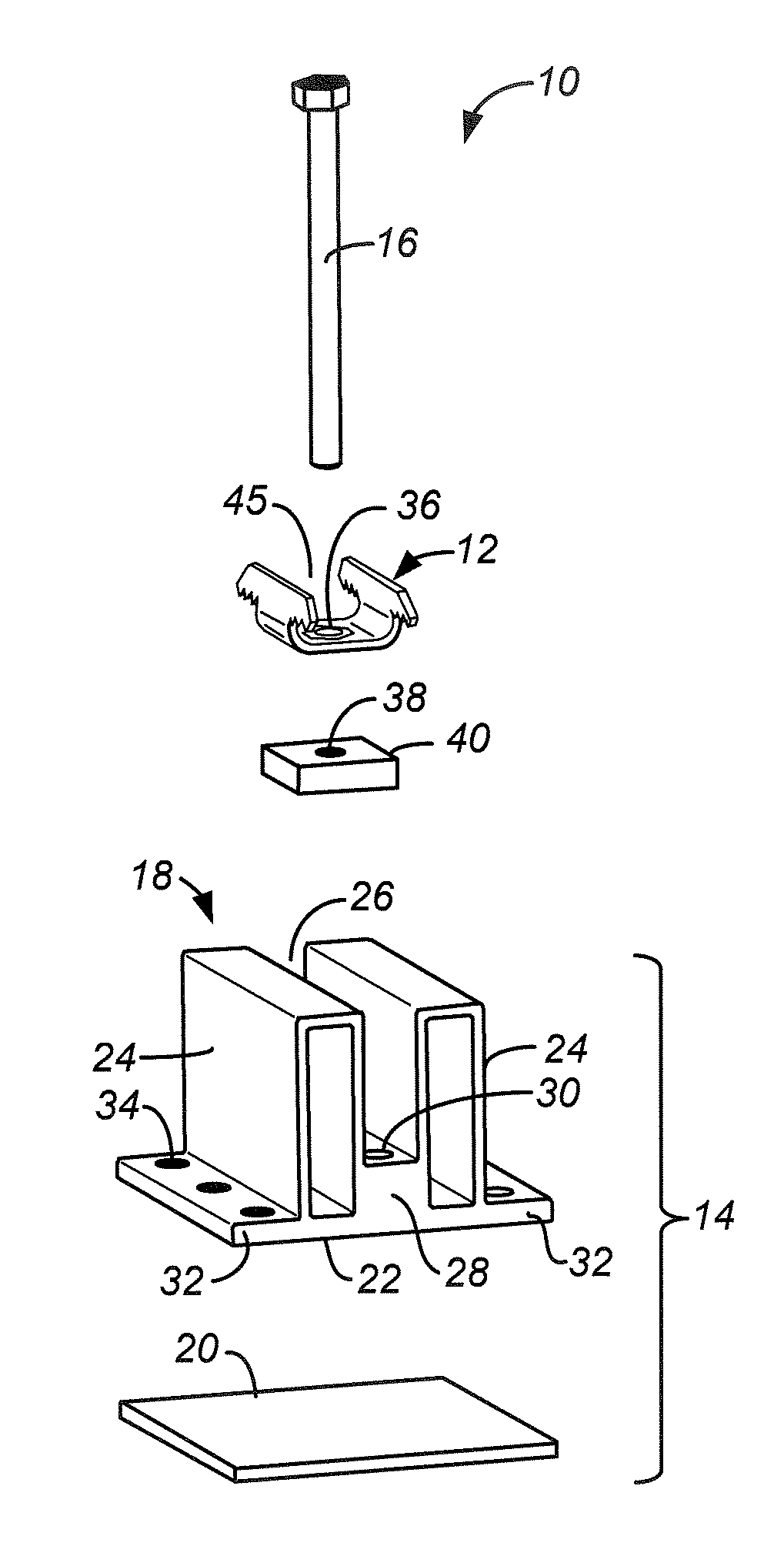
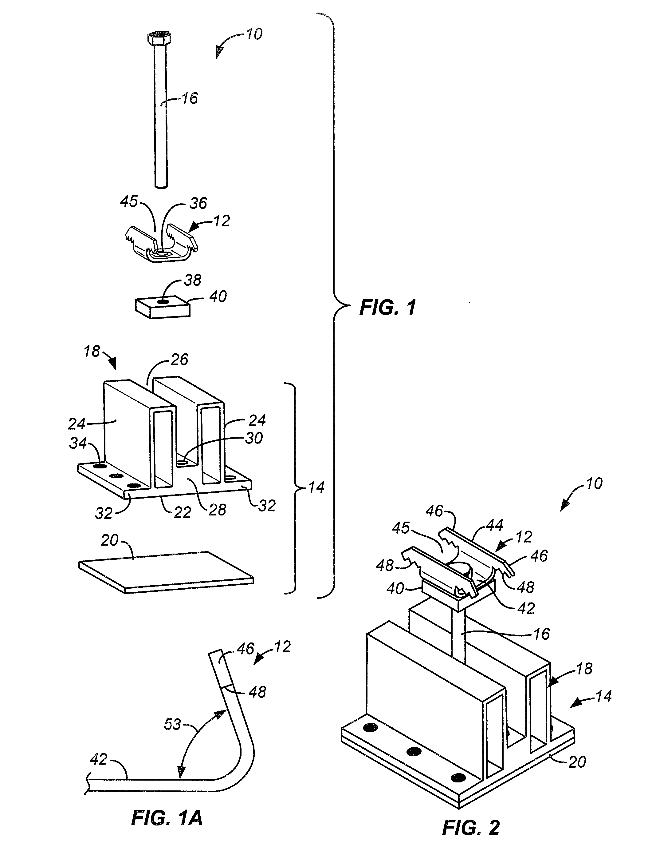
[0025]FIG. 1 is an exploded isometric view of one example of a clip assembly 10 made according to the invention. Assembly 10 includes a clip 12 secured to a second member 14 by a bolt 16. Second member 14 includes a base 18, typically of extruded aluminum or some other appropriate material, and a sealant 20 secured to th...


PUM


Abstract

An electrically conductive mounting / grounding clip, for use with a PV assembly of the type having an electrically conductive frame, comprises an electrically conductive body. The body has a central portion and first and second spaced-apart arms extending generally perpendicular to the central portion. Each arm has an outer portion with each outer portion having an outer end. At least one frame surface-disrupting element is at each outer end. The central portion defines a plane with the frame surface-disrupting elements pointing towards the plane. In some examples each arm extends from the central portion at an acute angle to the plane.

Description

CROSS-REFERENCE TO OTHER APPLICATIONS[0001]This application claims the benefit of provisional patent application No. 60 / 780,819 filed on 9 Mar. 2006, attorney docket number PWRL 1044-1 and provisional patent application No. 60 / 821,869 filed on 9 Aug. 2006, attorney docket number PWRL 1045-1, the disclosures of which are incorporated by reference.STATE SPONSORED RESEARCH OR DEVELOPMENT[0002]This invention was made with State of California support under California Commission Agreement Number 500-04-022. The Energy Commission has certain rights to this invention.BACKGROUND OF THE INVENTION[0003]This invention generally relates to the mounting of framed photovoltaic (PV) modules atop roofs and other support structures, where positive mechanical securement of the modules to the supporting base or structure is desirable and electrical grounding of accessible metal components, such as the PV module frame and ancillary mounting components, is required. Known combined mounting / grounding devi...

Claims


Application Information

Patent Timeline
Patent Type & Authority Applications(United States)
IPC IPC(8): H01R13/60A44B99/00
CPCF24J2/5245F24J2/5258F24J2002/5294H02S20/00Y02E10/47Y02E10/50H01R4/64F24S25/20F24S25/61F24S25/634F24S25/636F24S2025/021F24S2025/6008H02S20/23Y02B10/10Y10T24/44H01R13/73
Inventor LENOX, CARL J.
Owner SUNPOWER CORPORATION
Why Eureka
Try Eureka