Driving machine

Inactive Publication Date: 2007-09-20
HITACHI KOKI CO LTD
View PDF4 Cites 14 Cited by
  • Summary
  • Abstract
  • Description
  • Claims
  • Application Information

AI Technical Summary

Benefits of technology

[0028]According to the invention as set forth in claim 5, by moving the probe along the guide groove(s) in linking with the operation of the trigger switch when driving the fastening member, the probe can be retreated from the driving passage of the fastening member. This can enhance the operation efficiency of the driving machine.
[0029]According to the invention as set forth in claim 6

Problems solved by technology

Owing to this, the main body of the nail driving machine is large in size and heavy in weight, the operation efficiency of the nail driving machine is worsened, and the manufacturing cost thereof is increased.
This raises a problem that the impact strength of

Method used


Image

  • Driving machine
  • Driving machine
  • Driving machine

Examples


Example

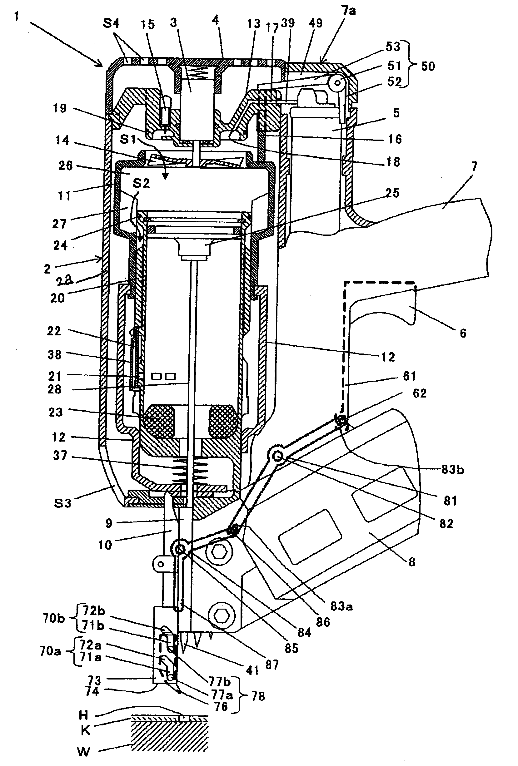
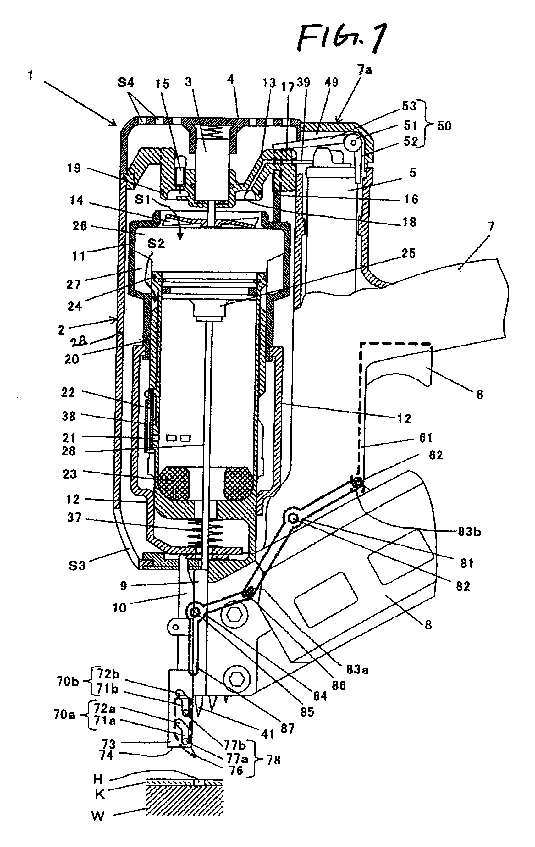
[0042]Now, description will be given below of an embodiment of the invention in which the invention is applied to a combustion-type nail driving machine with reference to the accompanying drawings.

[0043]FIG. 1 is a broken section view of a combustion-type nail driving machine according to the invention, showing an initial state thereof; FIG. 2 is a perspective view of a nail guide mechanism part of the combustion-type nail driving machine; FIG. 3 is a partial section view of the nail guide mechanism part of the combustion-type nail driving machine, showing a state just before starting to press the nail driving machine against a work; FIG. 4 is a partial section view of the nail guide mechanism part of the combustion-type nail driving machine, showing a state in which a work contact portion is contacted with the work after pressing the nail driving machine against the work; FIG. 5 is a broken section view of the combustion-type nail driving machine, showing a state in which a nail is...


PUM

PropertyMeasurementUnit
Forceaaaaaaaaaa

Abstract

In the driving machine, a work contact portion 73 including an end face 74 to be contacted with a connecting metal member (a member to be fastened) K is provided in a push lever 10, a probe 78 is movably provided in the work contact portion 73, the probe 78 is energized in the driving direction by a spring (energizing means) 75 to thereby project its leading end portion 76 from the end face 74 of the work contact portion 73, and, in a state where the main body of the driving machine is pressed against a work (a member to be driven) W, by operating a trigger switch 6, the probe 78 is retreated from the driving passage of a nail (a fastening member) 41.

Description

BACKGROUND[0001]1. Technical Field[0002]The present invention relates to a driving machine such as a nail driving machine which is used to drive a fastening member such as a nail into a member to be driven through a hole formed in a member to be fastened.[0003]2. Description of Related Art[0004]Like a nail driving machine which drives a piston using air pressure, combustion pressure or the like to strike a nail through a hole formed in a connecting metal member such as a member to be fastened, there is known a driving machine which drives a nail or the like into a previously determined hole positively; and, conventionally, as driving machines of this kind, there are proposed various types of driving machines.[0005]For example, as a power type nail driving machine, there are known several nail driving machines: one of them is a driving machine including a mechanism which, in order to align the axis of a nail driving portion, that is, the axis of a nail with a hole formed in a connect...

Claims


Application Information

Patent Timeline
IPC IPC(8): B25C5/06
CPCB25C1/047B25C7/00B25C1/08
Inventor OHMORI, YASUKI
Owner HITACHI KOKI CO LTD
Why Eureka
Try Eureka