Oscillation stabilization circuit

Active Publication Date: 2007-12-27
SAMSUNG ELECTRO MECHANICS CO LTD
View PDF3 Cites 2 Cited by
  • Summary
  • Abstract
  • Description
  • Claims
  • Application Information

AI Technical Summary

Benefits of technology

[0016]An advantage of the present invention is that it provides an oscillation stabilization detecting circuit which controls time for stabilization of oscillation signal by adjusting a bias current such that the time for stabilization of oscillation signal can be advanced.
[0017]Another advantage of the invention is that it provides an oscillation stabilization detecting circuit which can notice accurate stabilization time to a CPU, thereby enhancing operational efficiency of the CPU.
[0018]Additional aspect and advantages of the present general inventive concept will be set forth in part in the description which follows and, in part, will be obvious from the description, or may be learned by practice of the general inventive concept.
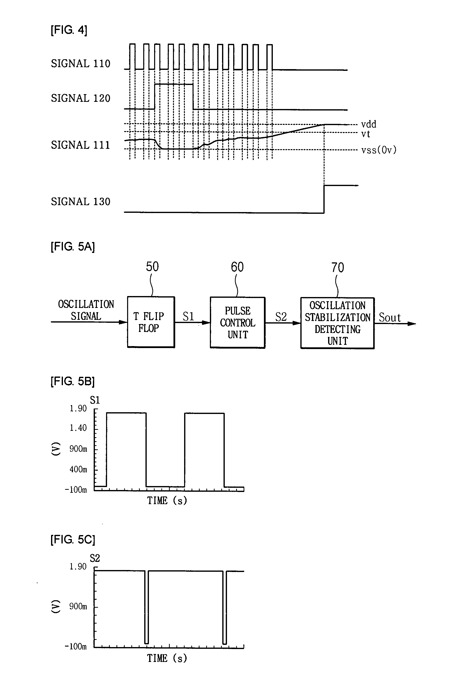
[0019]According to an aspect of the invention, an oscillation stabilization detecting circuit comprises a T flip flop receiving a pulse-type oscillation signal generated by oscillating a crystal oscillator and then dividing the oscillation signal to output; a pulse control unit including inverters and transistors, the pulse control unit converting the signal output from the T flip flop into a pulse-type signal starting from a high level and then outputting the converted signal; and an oscillation stabilization detecting unit including a capacitor charged with the signal output from the pulse control unit; and a plurality of transistors. The oscillation stabilization detecting unit controls charging time of the capacitor by adjusting a bias current and, after the charging time passes, outputs a stabilization signal to a CPU, the stabilization signal representing that the oscillation signal is stabilized.
[0020]Preferably, each of the transistors is provided with first to third terminals. Based on the magnitude of a voltage applied between the first and second terminals, the magnitude and direction of a current flowing from the second terminal to the third terminal are changed, and the first to third terminals are a gate, a source, and a drain, respectively.
[0021]Preferably, the oscillation stabilization detecting unit includes a capacitor; a bias current control section generating a bias current and controlling the magnitude of the bias current by using transistors; a first mirroring section mirroring the bias current output from the bias current control section; a second mirroring section connected to the first mirroring section and mirroring the bias current mirrored by the first mirroring section; a third mirroring section connected to the second mirroring section and mirroring the bias current mirrored by the second mirroring section; a capacitor charging section connected to the pulse control unit so as to charge the capacitor for the charging time controlled by the signal output from the pulse control unit; a comparator comparing the voltage charged in the capacitor with a reference voltage generated by the bias current mirrored through the third mirroring section; and an inverter inverting the signal output from the comparator and then outputting a stabilization signal to a CPU, the stabilization signal representing that the oscillation signal is stabilized.

Problems solved by technology

However, since the crystal oscillator oscillates using noise when initially operating, it takes a long time until an oscillation signal is stabilized, and accurate stabilization time cannot be noticed to a CPU.
Therefore, time required for the operation of the CPU is significantly wasted.
However, the conventional stabilization detecting circuit cannot control the charging time of the capacitor such that the time at which oscillation signal is stabilized cannot be adjusted.
Accordingly, it is impossible to advance the time for stabilization of oscillation signal.
Further, since the time for stabilization of oscillation signal cannot be adjusted, it is difficult to detect accurate stabilization time, and thus accurate stabilization time cannot be noticed to the CPU.
Therefore, a lot of time is wasted for the operation of the CPU such that operational efficiency of the CPU is degraded.

Method used


Image

  • Oscillation stabilization circuit
  • Oscillation stabilization circuit
  • Oscillation stabilization circuit

Examples


first embodiment

[0066]FIG. 7 is a circuit diagram of an oscillation stabilization detecting unit according to a first embodiment of the invention. As shown in FIG. 7, the oscillation stabilization detecting unit includes a capacitor C, a bias current control section 71, a first mirroring section 72, a second mirroring section 73, a third mirroring section 74, a capacitor charging section 75, a comparator 76, and an inverter 77.

[0067]The bias current control section 71 generates a bias current I and controls the magnitude of the bias current I by using MOS transistors.

[0068]FIG. 8 is a circuit diagram of the bias current control section of the invention. As shown in FIG. 8, the bias current control section 71 can be implemented by a plurality of MOS transistors. In FIG. 8, the descriptions will be focused on an embodiment using PMOS transistors. However, the invention is not limited to a specific type of MOS transistor. NMOS transistors or both of PMOS transistors and NMOS transistors can be used to...

second embodiment

[0084]FIG. 9 is a circuit diagram of an oscillation stabilization detecting unit according to a second embodiment of the invention. As shown in FIG. 9, the oscillation stabilization detecting unit includes a capacitor C, a bias current control section 71, a first mirroring section 72, a second mirroring section 73, a third mirroring section 74, a capacitor charging section 75, and a comparator 76.

[0085]The bias current control section 71 generates a bias current I and controls the magnitude of the bias current I by using MOS transistors.

[0086]The configuration of the bias current control section 71 and a process where a bias current is controlled by the current control section 71 are the same as those of the first embodiment which have been described with reference to FIG. 8.

[0087]The first mirroring section 72 mirrors the bias current I output from the bias current control section 71, and the second mirroring section 73 connected to the first mirroring section 72 mirrors the bias c...


PUM


Abstract

An oscillation stabilization detecting circuit comprises a T flip flop receiving a pulse-type oscillation signal generated by oscillating a crystal oscillator and then dividing the oscillation signal to output; a pulse control unit including inverters and transistors, the pulse control unit converting the signal output from the T flip flop into a pulse-type signal starting from a high level and then outputting the converted signal; and an oscillation stabilization detecting unit including a capacitor charged with the signal output from the pulse control unit; and a plurality of transistors. The oscillation stabilization detecting unit controls charging time of the capacitor by adjusting a bias current and, after the charging time passes, outputs a stabilization signal to a CPU, the stabilization signal representing that the oscillation signal is stabilized.

Description

CROSS-REFERENCE TO RELATED APPLICATIONS[0001]This application claims the benefit of Korean Patent Application No. 10-2006-0052471 filed with the Korea Intellectual Property Office on Jun. 12, 2006, the disclosure of which is incorporated herein by reference.BACKGROUND OF THE INVENTION[0002]1. Field of the Invention[0003]The present invention relates to an oscillation stabilization circuit which can control time, at which an oscillation signal is stabilized, by adjusting a bias current such that the time for stabilization of oscillation signal can be advanced. The oscillation stabilization circuit can detect accurate stabilization time and can notice the time to a CPU (Control Processing Unit), thereby enhancing operational efficiency of the CPU.[0004]2. Description of the Related Art[0005]In general, IC elements use an oscillation signal generated from a crystal oscillator provided outside.[0006]However, since the crystal oscillator oscillates using noise when initially operating, i...

Claims


Application Information

Patent Timeline
IPC IPC(8): H03L7/099
CPCH03L3/00G06F1/00G06F1/04
Inventor KWON, YONG ILKIM, MYEUNG SUPARK, TAH JOON
Owner SAMSUNG ELECTRO MECHANICS CO LTD
Why Eureka
Try Eureka