Method and system for reducing vehicle brake creep noise

a technology of vehicle brakes and creep noise, which is applied in the direction of braking systems, noise/vibration control, etc., can solve the problems of unfavorable vehicle operators, unfavorable vehicle operators, and inability to adjust the vehicle speed, so as to reduce or eliminate the creep noise from the brakes, reduce or eliminate the effect of noise reduction or elimination, and reduce the cost of implementation

Inactive Publication Date: 2007-09-20
KELSEY HAYES CO
View PDF6 Cites 23 Cited by
  • Summary
  • Abstract
  • Description
  • Claims
  • Application Information

AI Technical Summary

Benefits of technology

[0005] An embodiment contemplates a method of reducing creep groan noise emitted from brakes of a vehicle, the method comprising the steps of: determining a vehicle speed; determining a brake pressure; determining if the vehicle speed is less than a speed threshold; determining if the brake pressure is less than a pressure threshold; and adjusting the brake pressure in at least one but less than all of the brakes to thereby reduce the creep groan noise if the vehicle speed is less than the speed threshold and the brake pressure is less than the pressure threshold.
[0006] An embodiment contemplates a method of reducing creep groan noise emitted from brakes of a vehicle, the method comprising the steps of: determining a vehicle speed; determining a brake pressure; determining if the vehicle speed is less than a speed threshold and the vehicle is still moving; determining if the brake pressure is less than a pressure threshold; and reducing the brake pressure in at least one but less than all of the brakes and increasing the brake pressure in at least one of the brakes for which the brake pressure was not reduced in order to maintain an overall vehicle braking, if the vehicle speed is less than the speed threshold, the vehicle is still moving and the brake pressure is less than the pressure threshold.
[0008] An advantage of an embodiment is that the creep groan noise from the brakes is significantly reduced or eliminated, while still allowing a vehicle operator to travel at a desired low speed with the brakes partially actuated.
[0009] An advantage of an embodiment is that the creep noise is reduced or eliminated while not requiring the addition of or changes to the hardware of the brake system, thus minimizing the cost to implement this solution to creep noise concerns.

Problems solved by technology

The noise is generated as the pad / lining rubs on the rotor / drum.
Adjusting the vehicle speed is not practical since presumably the driver is intentionally driving at this very low speed.
Increasing or decreasing the overall brake pressure would change the vehicle speed—again something that would presumably be unwanted by the vehicle operator.

Method used


Image

  • Method and system for reducing vehicle brake creep noise
  • Method and system for reducing vehicle brake creep noise
  • Method and system for reducing vehicle brake creep noise

Examples


Embodiment Construction

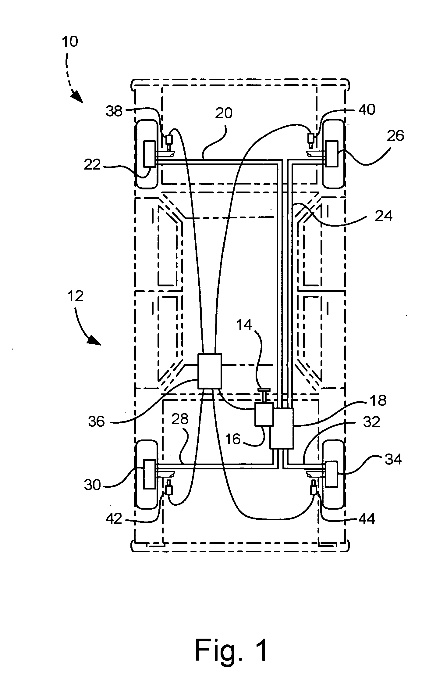
[0012]FIG. 1 illustrates a vehicle, indicated generally at 10, having a brake system, indicated generally at 12. The brake system 12 is a type where the brake pressure applied at one or more of the wheel brakes may be selectively different than the brake pressure applied at one or more of the other wheel brakes. Such systems are commonly referred to as slip control, anti-lock braking (ABS), traction control, and / or stability control.

[0013] The brake system 12 includes a brake pedal 14 that operatively engages a brake master cylinder 16, with or without a brake booster (not shown) interconnecting the two. The master cylinder 16 operatively engages an electro-hydraulic modulator 18 (also called an ABS actuator or a pressure modulator). The master cylinder 16 and modulator 18 may be two discrete, interconnected components or may be integrated into a single unit, if so desired. The modulator 18 may include solenoid operated valves (not shown) and an electric pump (not shown) for cyclin...


PUM


Abstract

The invention concerns a method and system for reducing vehicle brake creep noise by adjusting the pressure in selected wheel brake assemblies when the vehicle speed is less than a speed threshold and the brake pressure is less than a pressure threshold.

Description

BACKGROUND OF INVENTION [0001] The present invention relates generally to a vehicle braking system, and in particular to a vehicle braking system and method of operation that will reduce or eliminate noise from the brakes generated when a vehicle is creeping. [0002] For some automotive vehicles moving at very low speeds with the brakes partially actuated (i.e., with low brake pressures), a noise is generated by the brakes that is known as creep groan. The noise is generated as the pad / lining rubs on the rotor / drum. This creep noise is irritating to some vehicle occupants and so it is desirable to minimize or eliminate the noise. [0003] Since creep groan occurs at very low vehicle speeds with low brake pressures, a change in vehicle speed or a change in brake pressures may alleviate the creep noise problem. Adjusting the vehicle speed is not practical since presumably the driver is intentionally driving at this very low speed. Increasing or decreasing the overall brake pressure would...

Claims


Application Information

Patent Timeline
Patent Type & Authority Applications(United States)
IPC IPC(8): B60T8/32
CPCF16D65/0006B60T8/00
Inventor SCHMITT, OTTOBARTOL, MARKMERCIER, GREGOIRE
Owner KELSEY HAYES CO
Why Eureka
Try Eureka