Color filter array, imaging device, and image processing unit

a filter array and filter array technology, applied in the field of color filter arrays, imaging devices, image processing units, can solve the problems that the operation cannot be successful in the dumping readout method and the summing readout method, and achieve the effect of preventing a decrease in resolution

Inactive Publication Date: 2007-09-20
SONY CORP
View PDF9 Cites 68 Cited by
  • Summary
  • Abstract
  • Description
  • Claims
  • Application Information

AI Technical Summary

Benefits of technology

[0036] Accordingly, the present invention provides a color filter array, an imaging device, and an image processing unit capable of sufficiently preventing a decrease in resolution and the occurrence of a false color and supporting dumping and summing processes of signals from pixels even when filters of colors more than that of the Bayer arrangement are used.
[0043] According to the present invention, a color filter array, an imaging device, and an image processing unit capable of sufficiently preventing a decrease in resolution and the occurrence of a false color and supporting dumping and summing processes of signals from a plurality of pixels even when filters of colors more than that of the Bayer arrangement are used.

Problems solved by technology

In addition, a successful operation cannot be performed in the dumping readout method and the summing readout method.

Method used


Image

  • Color filter array, imaging device, and image processing unit
  • Color filter array, imaging device, and image processing unit
  • Color filter array, imaging device, and image processing unit

Examples


first exemplary embodiment

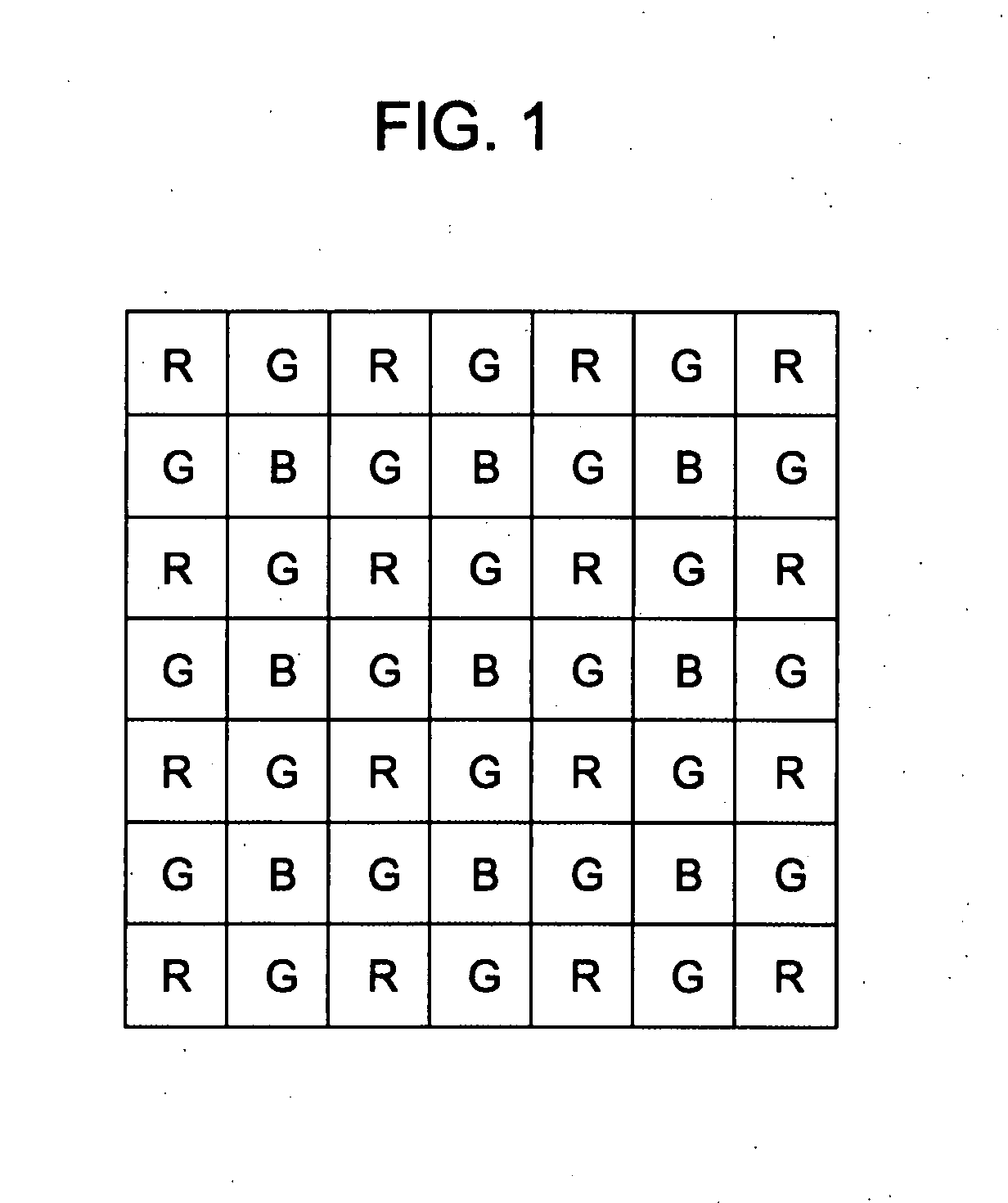
[0062] According to a first exemplary embodiment, a filter arrangement is used for an imaging device in which one of a plurality of filters having different color separation characteristics (i.e., colors) is bonded to each pixel. The filter arrangement includes four colors or more. A color C1 is arranged in a checkered pattern. Some or all of the other colors are randomly arranged at pixel locations at which the color C1 is not present.

[0063] As used herein, the term “color” refers to a filter or a pixel value of that color obtained from the filter.

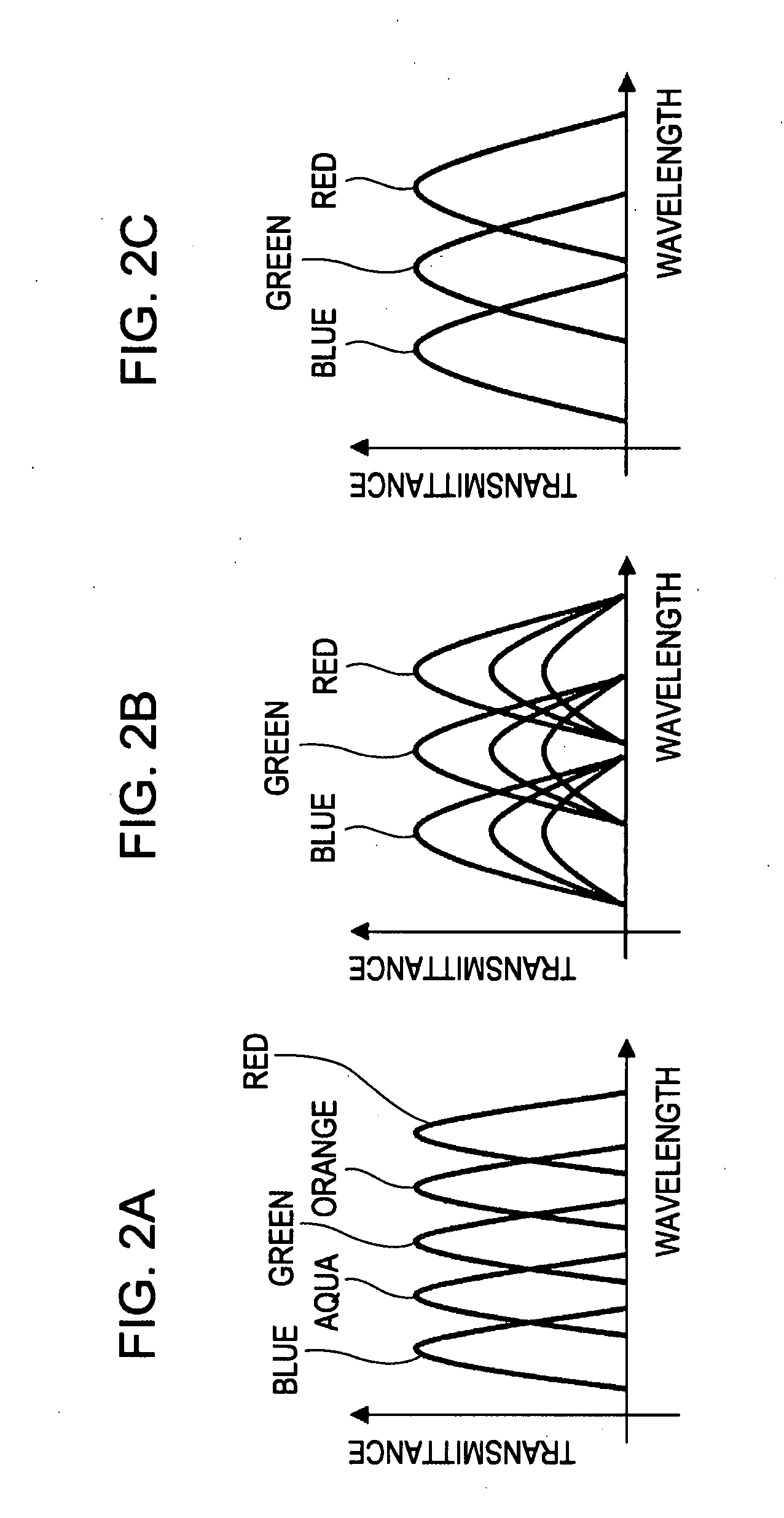
[0064] In such a color arrangement, since color filters of four colors or more are employed, the performance of color reproduction and the dynamic range can be improved compared with a three-color filter arrangement.

[0065] Since the color C1 has a checkered pattern, a correlation process that is applied to a G-color checkered pattern of the Bayer arrangement can be applied to the C1 checkered pattern. Accordingly, a signal in a high-fr...

second exemplary embodiment

[0208] According to a second exemplary embodiment, a color filter arrangement is obtained by replacing the C1 color filters arranged in a checkered pattern in the color filter arrangement according to the first exemplary embodiment with regularly arranged filters of two colors C1a and C1b.

[0209] As described in Japanese Unexamined Patent Application Publication No. 2005-160044, a new color C1c is generated on the basis of the colors C1a and C1b. Thereafter, using the regular arrangement of the C1a and C1b color filters, the color C1c can be interpolated at the locations of all of the pixels at which the C1a or C1b color filters are present.

[0210] The filter arrangement in which the C1c color filters are arranged in place of the C1a and C1b color filters is the same as the filter arrangement described in the first exemplary embodiment.

[0211] That is, according to the second exemplary embodiment, the color filter array provides the same advantage as that of the first exemplary embo...


PUM


Abstract

A color filter array includes a plurality of filters, each having one of a plurality of types of spectral sensitivity and being disposed at the location of a corresponding one of a plurality of pixels. The filters of a predetermined type selected from among the plurality of types are arranged at the locations of the pixels in a checkered pattern, and the filters of some or all of the other types are randomly arranged at the pixel locations at which the filters of the predetermined type are not present.

Description

CROSS REFERENCES TO RELATED APPLICATIONS [0001] The present invention contains subject matter related to Japanese Patent Application JP 2006-069541 filed in the Japanese Patent Office on Mar. 14, 2006, the entire contents of which are incorporated herein by reference. BACKGROUND OF THE INVENTION [0002] 1. Field of the Invention [0003] The present invention relates to a color filter array, an imaging device, and an image processing unit used for an image capturing apparatus, such as a digital camera using a solid-state imaging device. [0004] 2. Description of the Related Art [0005] Single-plate color image capturing apparatuses that include an image processing unit are known. In the image capturing apparatuses, a color filter is bonded to each of a plurality of pixels of a single-plate solid-state imaging device and the image processing unit allocates all colors to the position of each pixel using a mosaic image of colors captured by the imaging device. [0006] In such image capturing...

Claims


Application Information

Patent Timeline
Patent Type & Authority Applications(United States)
IPC IPC(8): H04N9/64H01L27/14H04N9/07
CPCH04N9/045H01L27/146F21V9/08H04N25/135H04N23/843H04N25/134
Inventor NOMURA, YOSHIKUNIMITSUNAGA, TOMOO
Owner SONY CORP
Why Eureka
Try Eureka