Electro-optical device and electronic apparatus

Inactive Publication Date: 2007-09-20
SEIKO EPSON CORP
View PDF10 Cites 9 Cited by
  • Summary
  • Abstract
  • Description
  • Claims
  • Application Information

AI Technical Summary

Benefits of technology

[0025]This configuration can display a b

Problems solved by technology

However, the art disclosed in JP-A-2000-214421 concerns an electrically controlled birefringence mode liquid crystal display device, and it cannot be applie

Method used


Image

  • Electro-optical device and electronic apparatus
  • Electro-optical device and electronic apparatus
  • Electro-optical device and electronic apparatus

Examples


examples

[0067]Simulations were performed before the property of the liquid crystal material forming the liquid crystal layer 50 and parameters of the liquid crystal display device 100 were determined. The parameters have been described with reference to FIGS. 12A and 12B. The simulation results will be described with reference to the graphs of FIGS. 5 to 11.

[0068]FIG. 5 shows the relationship between the elastic constant K11 for splay distortion of the liquid crystal material and the afterimage level L. FIG. 6 shows the relationship between the elastic constant K33 for bend distortion of the liquid crystal material and the afterimage level L. In the graph of FIG. 5, the horizontal axis indicates the elastic constant K11 (pN), and the vertical axis indicates the afterimage level L. In the graph of FIG. 6, the horizontal axis indicates the elastic constant K33 (pN), and the vertical axis indicates the afterimage level L.

[0069]The afterimage level L indicates, on a scale of 1 to 5, the level o...


PUM


Abstract

An electro-optical device includes a pair of substrates, and a liquid crystal layer between the substrates. At least one of the substrates has a plurality of scanning lines, a plurality of data lines, and pixel electrodes. The data lines intersect with the scanning lines. The pixel electrodes are disposed in a matrix and correspond to the intersections of the scanning lines with the data lines. When the elastic constant for splay distortion of a liquid crystal material forming the liquid crystal layer is K11, the elastic constant for bend distortion thereof is K33, the dielectric anisotropy thereof is Δε, and the rotational viscosity thereof is γ, the liquid crystal material satisfies the following conditions: 7 pN≦K11≦14 pN; 10 pN≦K33≦16 pN; 12≦Δ∈≦15; and 50 mPa·s≦γ≦100 mPa·s.

Description

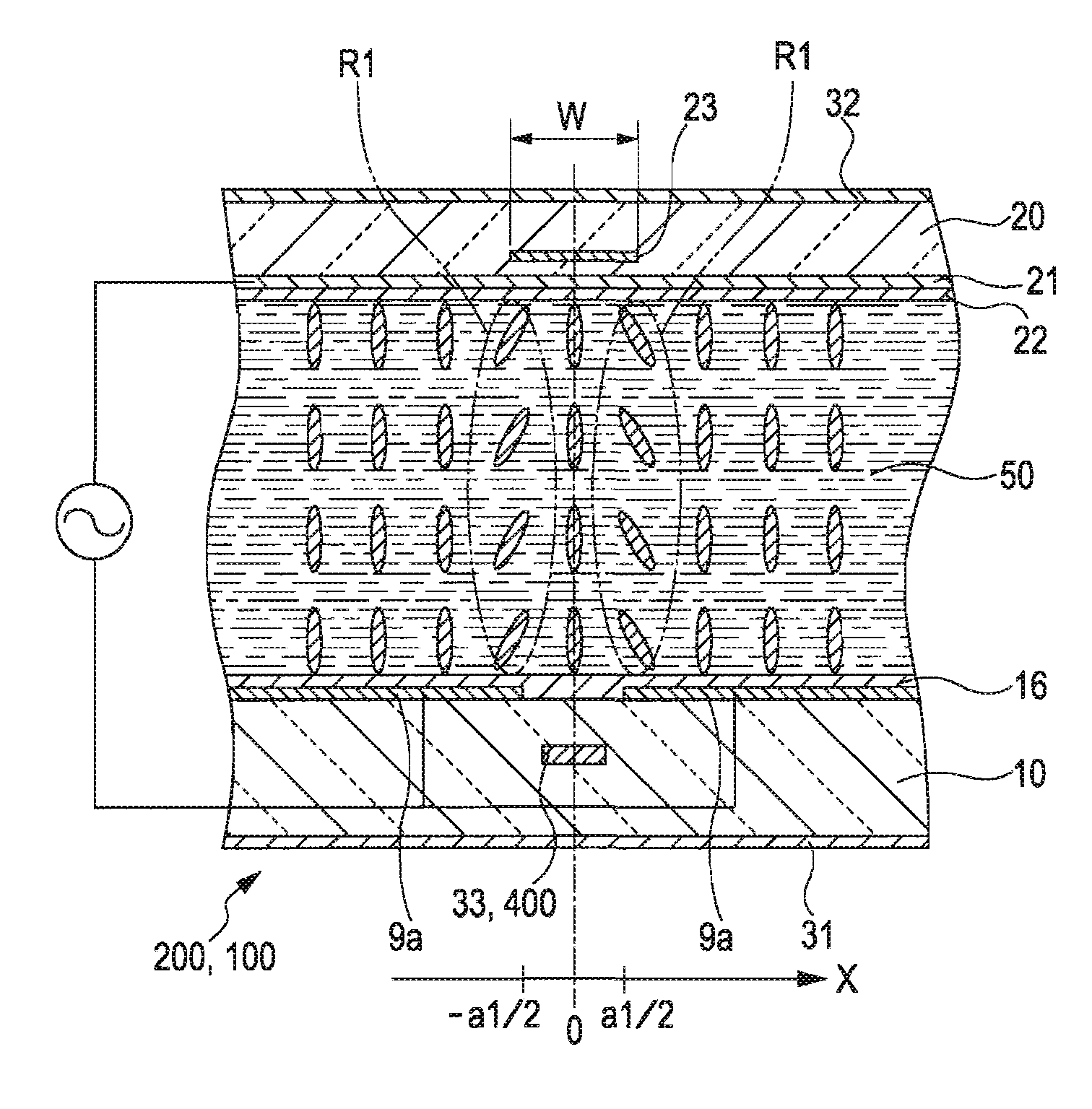
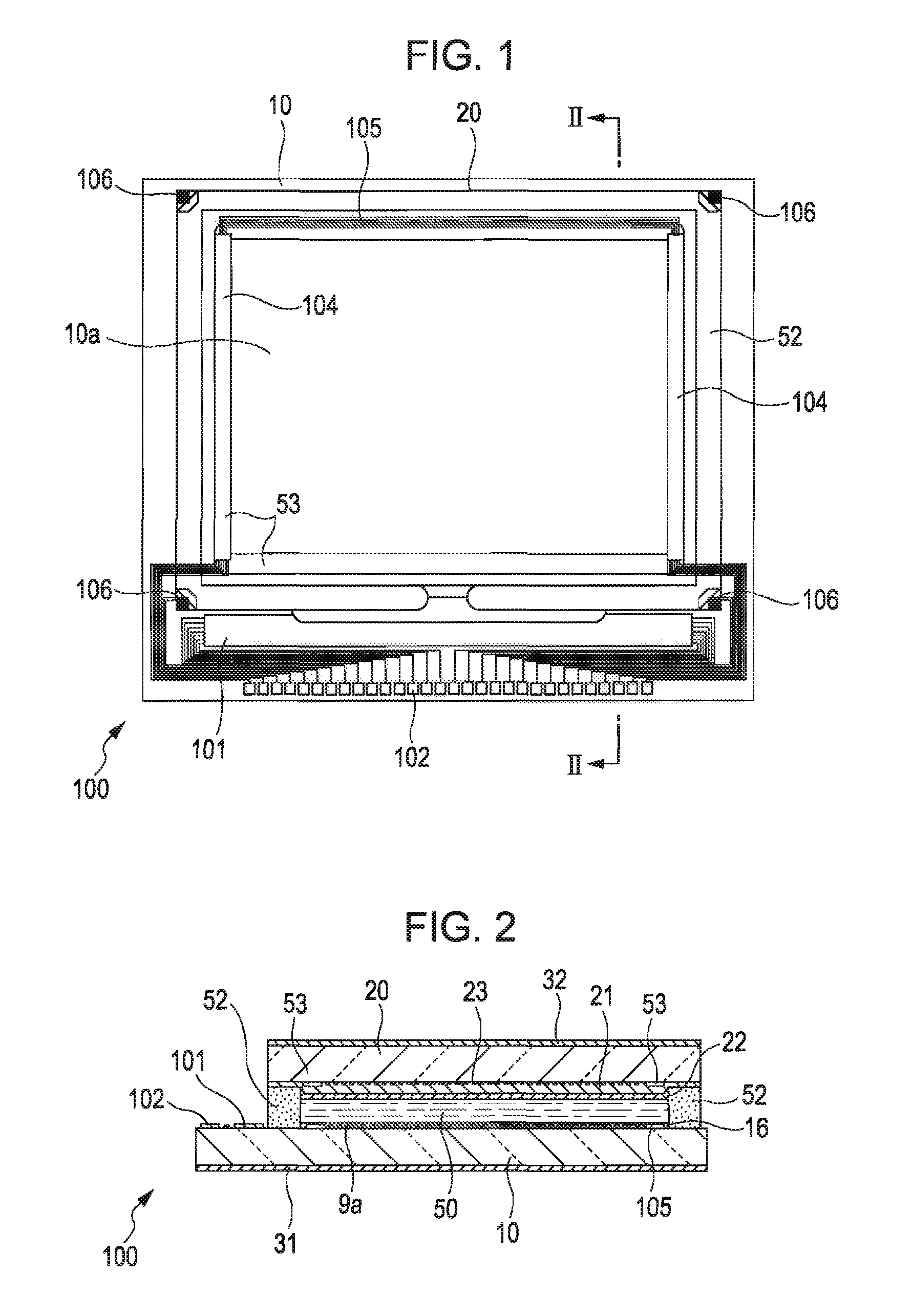
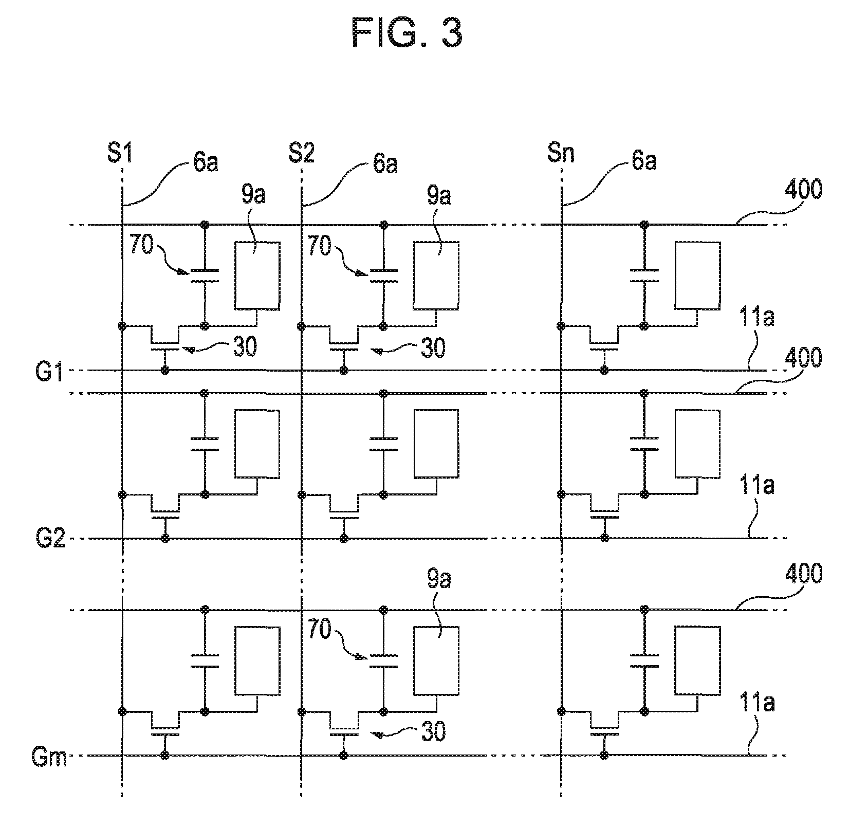
BACKGROUND[0001]1. Technical Field[0002]The present invention relates to an electro-optical device and an electronic apparatus, and more specifically, relates to an electro-optical device including a pair of substrates and a liquid crystal layer therebetween, and an electronic apparatus including the electro-optical device.[0003]2. Related Art[0004]An electro-optical device, or more specifically a so-called twisted nematic (hereinafter referred to as TN) mode liquid crystal display device that operates in a TN mode, includes a liquid crystal layer between a pair of substrates such as glass substrates or quartz substrates. One of the substrates has a plurality of pixel electrodes disposed thereon in a matrix. The other substrate has a common electrode disposed thereon. FIGS. 12 to 14 illustrate the general configuration and the operation of a part of a TN mode liquid crystal display device 200 where pixel electrodes 9a are formed.[0005]A TN mode liquid crystal display device 200 incl...

Claims


Application Information

Patent Timeline
IPC IPC(8): G02F1/1335
CPCG02F1/0045G02F1/133707G02F2001/13373G02F1/1395G02F1/133753G02F1/13373
Inventor ONO, TAKEHIRO
Owner SEIKO EPSON CORP
Why Eureka
Try Eureka