Zoom lens system, imaging device and camera

Inactive Publication Date: 2007-09-20
PANASONIC CORP
View PDF11 Cites 13 Cited by
  • Summary
  • Abstract
  • Description
  • Claims
  • Application Information

AI Technical Summary

Benefits of technology

[0020]An object of the present invention is to provide: a zoom lens system that has a high resolution, sufficient periphery illuminance ensured in the entire variable magnification range and high capabilit

Problems solved by technology

This causes a tendency of size increase in the entire optical instrument.
This reduces the thickness of the entire first lens unit and hence the size of the optical system.
This causes a problem of insufficiency in the compensation of curvature of field.
Nevertheless, in this case, although the diameter of the lens can be constructed comparatively small, when the first lens unit is composed of two lenses, the optical power becomes excessive in the object side lens.
This causes a problem of increase in the overall optical length at the time of non-use.
Further, t

Method used


Image

  • Zoom lens system, imaging device and camera
  • Zoom lens system, imaging device and camera
  • Zoom lens system, imaging device and camera

Examples


embodiments 1 to 4

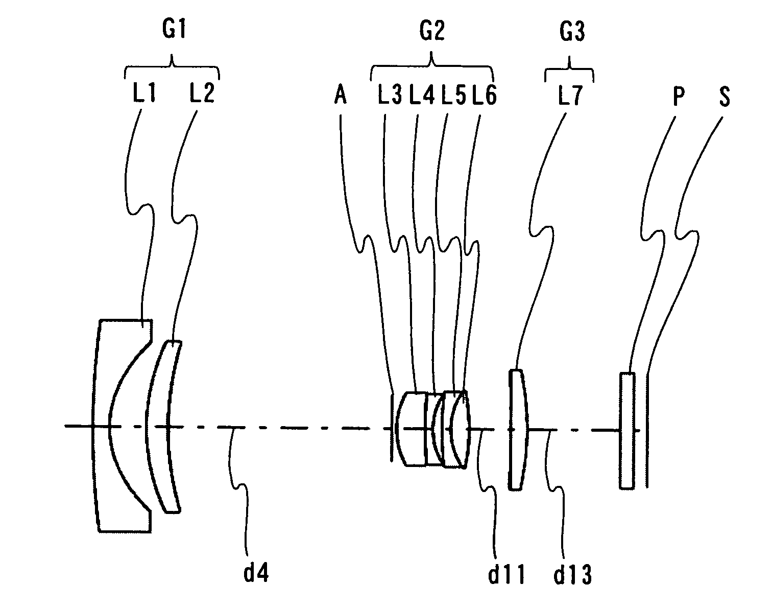
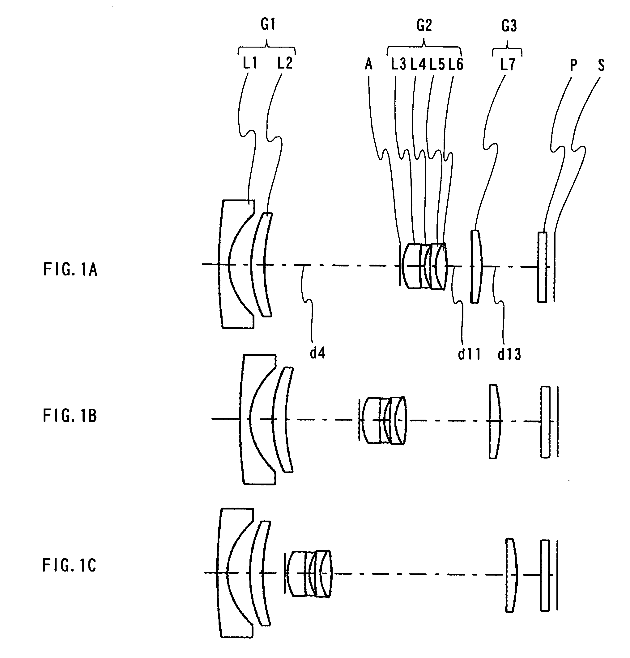
[0076]FIGS. 1A to 1C are configuration diagrams of a zoom lens system according to Embodiment 1. FIGS. 3A to 3C are configuration diagrams of a zoom lens system according to Embodiment 2. FIGS. 5A to 5C are configuration diagrams of a zoom lens system according to Embodiment 3. FIGS. 7A to 7C are configuration diagrams of a zoom lens system according to Embodiment 4. Each of FIGS. 1A to 1C, 3A to 3C, 5A to 5C, and 7A to 7C shows a zoom lens system in an infinity in-focus condition. FIGS. 1A, 3A, 5A and 7A show the lens construction at a wide-angle limit (the shortest focal length condition: focal length fW). FIGS. 1B, 3B, 5B and 7B show the lens construction at a middle position (the middle focal length condition: focal length fM=√(fW*fT)). FIG. 1C, 3C, 5C and 7C show the lens construction at a telephoto limit (the longest focal length condition: focal length fT).

[0077]Each zoom lens system according to Embodiments 1 to 4, in order from the object side to the image side, comprises: ...

embodiment 5

[0151]FIG. 9 is a schematic construction diagram of a digital still camera according to Embodiment 5. In FIG. 9, the digital still camera comprises: an imaging device including a zoom lens system 1 and an image sensor 2 that is a CCD; a liquid crystal display monitor 3, and a body 4. The employed zoom lens system 1 is the zoom lens system according to Embodiment 1. In FIG. 9, the zoom lens system 1 comprises a first lens unit G1, a diaphragm A, a second lens unit G2, and a third lens unit G3. In the body 4, the zoom lens system 1 is arranged on the front side, while the image sensor 2 is arranged on the rear side of the zoom lens system 1. The liquid crystal display monitor 3 is arranged on the rear side of the body 4, while an optical image of a photographic object acquired through the zoom lens system 1 is formed on the image surface S.

[0152]The lens barrel comprises a main barrel 5, a moving barrel 6, and a cylindrical cam 7. When the cylindrical cam 7 is rotated, the first lens ...

example 1

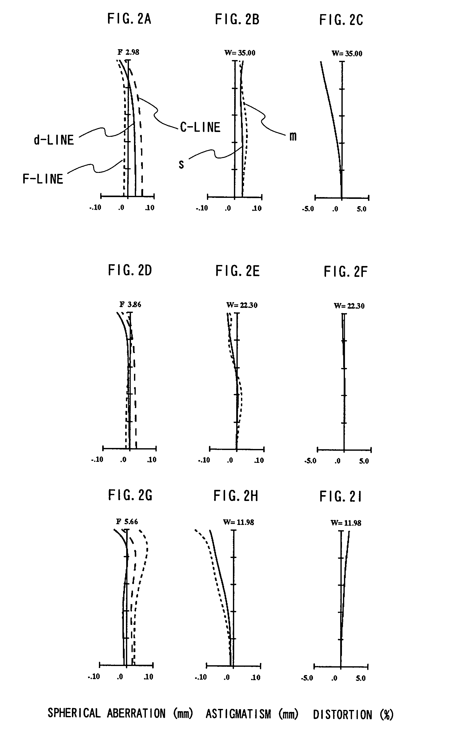
[0156]A zoom lens system of Example 1 corresponds to Embodiment 1 shown in FIGS. 1A to 1C. Table 1 shows the lens data of the zoom lens system of Example 1. Table 2 shows the aspherical data. Table 3 shows the focal length f, the F-number, the view angle 2ω, the overall optical length L, and the variable axial distance data d4, d11 and d13, when the shooting distance is infinity.

TABLE 1LensLens unitelementSurfacerdndνdG1L1151.8241.1001.80541.0*26.2872.433L2312.8871.4002.40017.0*417.651VariableDiaphragm5∞0.300G2L3*64.6171.9001.80541.0L4730.1910.5001.71729.584.0690.600L5919.2890.6001.62036.3L6104.4131.2001.58961.311−12.764VariableG3L712−237.8731.1001.66555.2*13−15.297VariableP14∞0.9001.51764.215∞0.870

TABLE 2SurfacekABCDE2−3.612E−017.170E−06−3.185E−06−1.903E−09−1.340E−090.000E+0040.000E+00−9.258E−051.154E−060.000E+000.000E+000.000E+0060.000E+00−5.397E−04−1.839E−051.169E−07−3.148E−080.000E+00130.000E+004.422E−04−5.274E−056.216E−06−3.426E−077.090E−09

TABLE 3AxialWide-angleMiddleTelephotod...


PUM


Abstract

A zoom lens system comprising a first lens unit of negative power, a second lens unit of positive power and a third lens unit of positive power, wherein in zooming, the lens units move respectively along an optical axis so that an interval of first lens unit and second lens unit decreases while an interval of second lens unit and third lens unit changes with variable magnification, the first lens unit comprises one object side negative lens element and one image side positive lens element, which have an aspheric surface, and the conditions: n12>1.88, ν12<26 and 3.0<f3/fW<5.5 (ωW>30, n12 and ν12 are refractive index and Abbe number, respectively, of the image side positive lens element of the first lens unit, f3 is a composite focal length of the third lens unit, fW is a focal length of the entire zoom lens system at a wide-angle limit) are satisfied.

Description

CROSS-REFERENCE TO RELATED APPLICATION[0001]This application is based on application No. 2006-64710 filed in Japan on Mar. 9, 2006, the content of which is hereby incorporated by reference.BACKGROUND[0002]1. Technical Field[0003]The present invention relates to a zoom lens system, an imaging device and a camera. In particular, the present invention relates to: a zoom lens system that has a high resolution, sufficient periphery illuminance ensured in the entire variable magnification range and high capability of compensating curvature of field, and that still has a short overall optical length at the time of non-use; an imaging device employing this zoom lens system; and a camera employing this imaging device.[0004]2. Description of the Background Art[0005]In the prior art, a large number of optical instruments have been developed that form an image of a photographic object onto an image sensor through a lens and then acquire the object image as an image. Recently, products such as d...

Claims


Application Information

Patent Timeline
IPC IPC(8): G02B15/14
CPCG02B15/177G02B15/143507
Inventor KURIOKA, YOSHIAKI
Owner PANASONIC CORP
Why Eureka
Try Eureka