
Radio communication apparatus and radio communication system

a radio communication and radio communication technology, applied in direction finders using radio waves, instruments, measurement devices, etc., can solve the problems of inability to easily obtain the positional relationship of two or three radio communication apparatuses, inability to introduce and increased cost of introducing gps and exclusive measuring devices

Inactive Publication Date: 2007-09-20
RICOH KK
View PDF4 Cites 18 Cited by
  • Summary
  • Abstract
  • Description
  • Claims
  • Application Information

AI Technical Summary

Benefits of technology

[0013]It is an object of the present invention to at lea...

Problems solved by technology

However, when a GPS and an exclusive measuring device are introduced to obtain a position of the other radio communication apparatus in a conventional office supporting system such as an electronic meeting system, cost of introducing the GPS and the exclusive measuring device increases.
However, according to the technique of WiMedia (MBOA), directivity of waves cannot be controlled.
Therefore, positional relationship of two or three radio communication apparatuses cannot be obtained easily, and four or more radio communication apparatuses are necessary.
Specifically, when two or three radio communication apparatuses are used, a plane surface cannot be specified, and it is difficult to obtain position information.
However, a position of the other station cannot be specified and it can be only known that the other station is somewhere around the self station on the spherical surface.

Method used


Image

  • Radio communication apparatus and radio communication system
  • Radio communication apparatus and radio communication system
  • Radio communication apparatus and radio communication system

Examples


Embodiment Construction

[0032]Exemplary embodiments of the present invention will be explained below in detail with reference to the accompanying drawings.

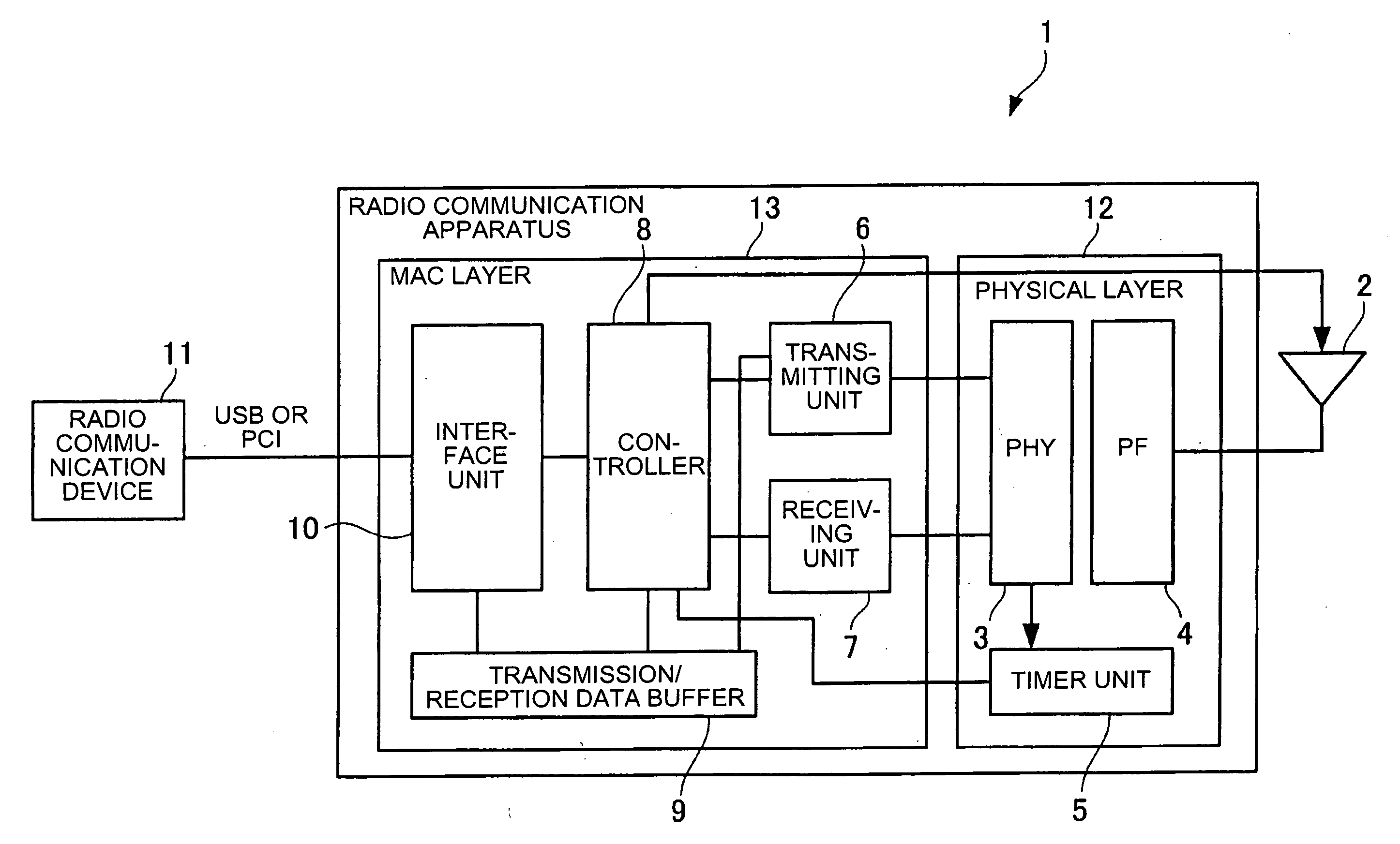
[0033]FIG. 1 is a block diagram of a configuration of a radio communication apparatus according to one embodiment of the present invention. In this embodiment, the radio communication apparatus includes a variable directivity antenna described later, thereby obtaining position information using two radio communication apparatuses.

[0034]A radio communication apparatus 1 includes a variable directivity antenna 2, a coding and decoding unit 3 (described as PHY in FIG. 1), and a radio frequency unit 4 (described as RF in FIG. 1). The variable directivity antenna 2, the coding and decoding unit 3, and the radio frequency unit 4 constitute a physical layer 12 in the radio communication apparatus 1.

[0035]The radio communication apparatus 1 includes a transmitting unit 6, a receiving unit 7, a controller 8, a transmission / reception data buffer 9, and an interfac...


PUM


Abstract

A radio communication apparatus includes a variable directivity antenna and a control unit and performs radio communication with another radio communication apparatus. The control unit calculates a position of the another radio communication apparatus by measuring a distance to the another radio communication apparatus and measuring directivity of the another radio communication apparatus by switching directivity of the wave of radio communication using the variable directivity antenna with a MEMS switch. Moreover, the control unit controls the output of the variable directivity antenna according to the calculated position of the another radio communication apparatus.

Description

CROSS-REFERENCE TO RELATED APPLICATIONS[0001]The present document incorporates by reference the entire contents of Japanese priority document, 2006-075027 filed in Japan on Mar. 17, 2006.BACKGROUND OF THE INVENTION[0002]1. Field of the Invention[0003]The present invention relates to a radio communication apparatus and a radio communication system, and, more particularly to a radio communication apparatus and a radio communication system that obtain position information of another communication apparatus.[0004]2. Description of the Related Art[0005]Conventionally, a technique of obtaining a position of a mobile station using at least three base stations, preferably four or more base stations, is known (Japanese Patent Application Laid-open No. 2004-301850).[0006]There is also known a technique of carrying out an electronic conference through data communications between plural clients and a server, by displaying characters on a large display screen (Japanese Patent Application Laid-op...

Claims


Application Information

Patent Timeline
IPC IPC(8): H04M11/04
CPCG01S3/72H04W64/00G01S5/12G01S5/0289
Inventor SATOH, TETSUYA
Owner RICOH KK
Learn More