
Sleep Mode Systems and Methods

Inactive Publication Date: 2007-09-20
INTELLECTUAL VENTURES I LLC
View PDF6 Cites 56 Cited by
  • Summary
  • Abstract
  • Description
  • Claims
  • Application Information

AI Technical Summary

Problems solved by technology

Although such sleep mode techniques are widely used, there are limitations in their use depending on the application and / or device.
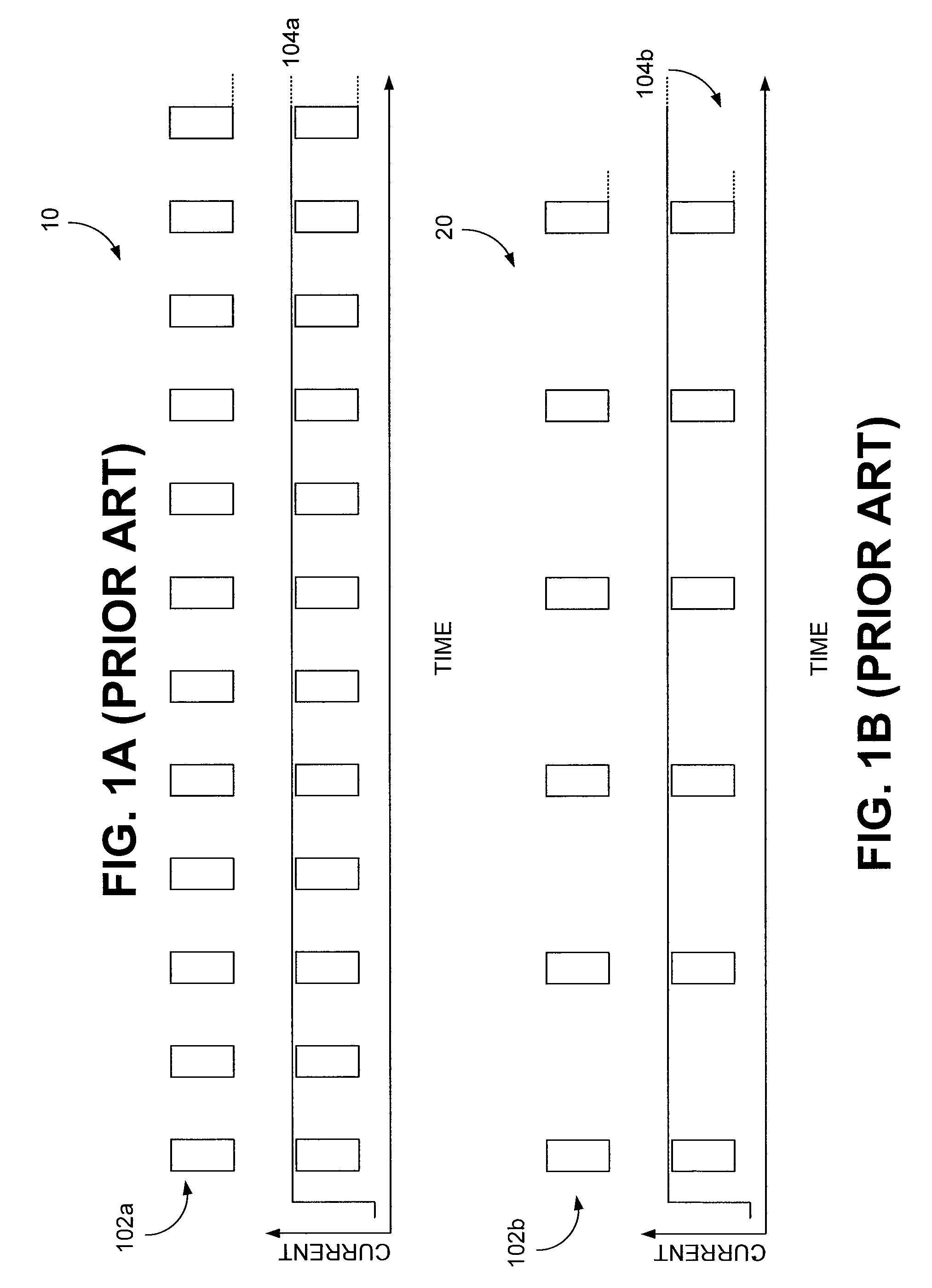
In some implementations, the time between transmissions or the transmission of frames may prevent the commencement of the sleep and wake modes, or at least negate any benefit in terms of power consumption.
Further, such systems can draw a high amount of current (and hence consume a significant amount of power) during transmission.

Method used


Image

  • Sleep Mode Systems and Methods
  • Sleep Mode Systems and Methods
  • Sleep Mode Systems and Methods

Examples


Embodiment Construction

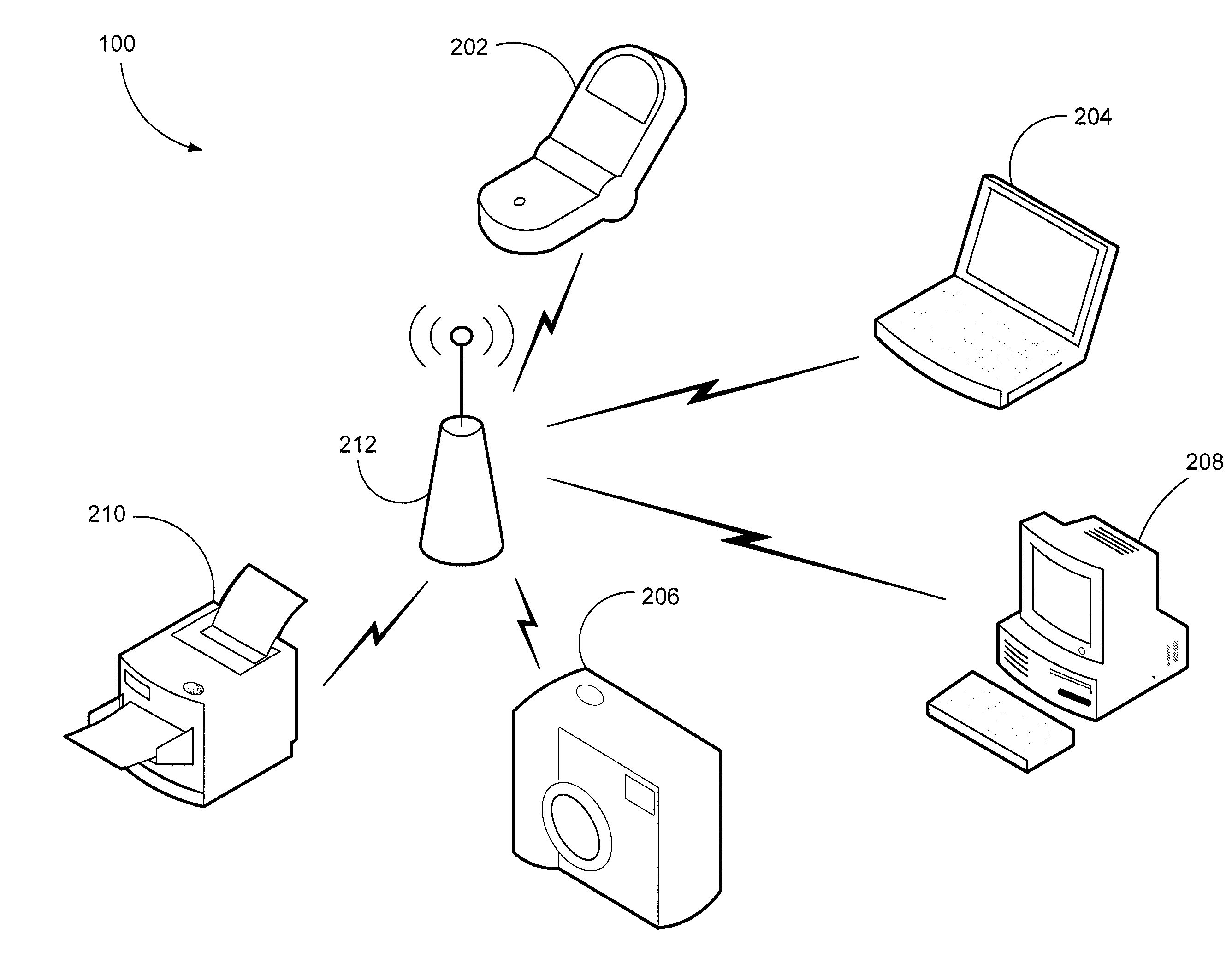
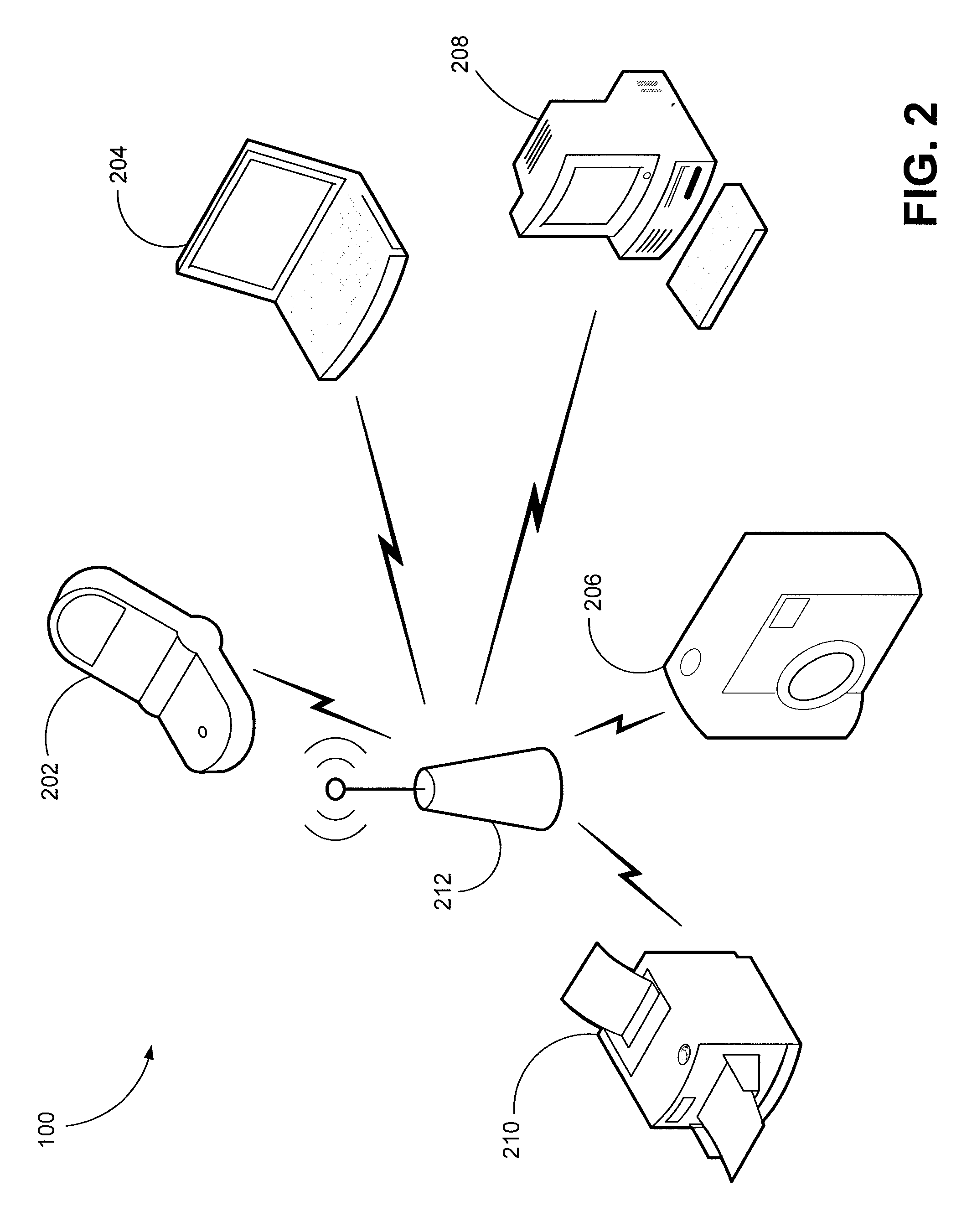
[0019]Disclosed herein are various embodiments of sleep mode systems and methods, herein simply sleep mode systems. Such sleep mode systems implement a repeated process of queuing (e.g., buffering or caching) a plurality of frames during a sleep mode, commencing a wake mode to transmit the queued (or buffered) frames in a burst transmission, and then returning to the sleep mode to collect the frames for subsequent burst transmission during a wake mode. That is, devices (e.g., wired, or more typically, wireless) employing certain embodiments of the sleep mode systems and methods buffer several frames in memory, then send the buffered frames out as one contiguous packet burst with minimal interframe spacing. The buffering time is used to put the device employing the sleep mode systems and methods in a low power mode. In other words, implementing such sleep mode methods enables a wireless local area network (WLAN) device, and in particular, a WLAN device equipped with a slow host proce...


PUM


Abstract

Embodiments of sleep mode systems and methods are disclosed. In one method embodiment, among others, a sleep mode method comprises commencing a sleep mode, and during the sleep mode, queuing a plurality of frames for a burst transmission.

Description

CROSS-REFERENCE TO RELATED APPLICATION[0001]This application claims priority to copending U.S. provisional application having Ser. No. 60 / 784,971, filed on Mar. 20, 2006, which is entirely incorporated herein by reference.BACKGROUND[0002]1. Field of the Invention[0003]The present disclosure is generally related to communication systems, and, more particularly, is related to wireless communication systems and methods.[0004]2. Related Art[0005]Wireless communication systems are widely deployed to provide various types of communication, such as voice, data, and so on. Much has changed in the way of wireless devices from the early days of bulky walkie-talkies and base-mounted car phones. Miniaturization of components and advancements in protocols and methods over the years have resulted in cell phones that can rest on an ear lobe, multi-media entertainment devices like the IPOD that provide hours of entertainment while fitting comfortably in the palm of one's hand, or digital cameras th...

Claims


Application Information

Patent Timeline
IPC IPC(8): H04Q7/20H04W52/02H04W80/06
CPCH04W80/06H04W52/0251Y02D30/70
Inventor CARTER, TRENT R.
Owner INTELLECTUAL VENTURES I LLC
Learn More