
Messaging device

a technology of vibration-type and sonic device, which is applied in the field of vibration-type massaging device, can solve the problems of compromising the desired vibrating contact between the motor c, generating great noise, and affecting the operation of the device, so as to maintain the effect of its stability

Inactive Publication Date: 2007-09-20
WEN TSAI YU +2
View PDF5 Cites 8 Cited by
  • Summary
  • Abstract
  • Description
  • Claims
  • Application Information

AI Technical Summary

Benefits of technology

[0007] It is therefore an object of the present invention to provide a massaging device comprising a housing and a vibration-type motor secured to a channel of the housing wherein the housing comprises means for absorbing the force of shocks and jarring generated by the activating motor, thereby maintaining its stability during operation.
[0009] In one aspect of the present invention the housing can be mass produced easily, the motor is precisely mounted in the channel of the housing, and the housing further comprises a base having a buffer arrangement for further absorbing the force of shocks and jarring generated by the activating motor.

Problems solved by technology

However, the prior art suffered from a disadvantage.
This may compromise the desired vibrating contact between the motor C and the vibration member F. Such condition is worse when the base A is inclined.
As an end, great noise is generated and the vibration becomes irregular.
Such soldering may not precisely mount both the bracket B on the base A and the motor C in the bracket B. As a result, the eccentric shaft of the motor C may shift undesirably.

Method used


Image

  • Messaging device
  • Messaging device
  • Messaging device

Examples


Embodiment Construction

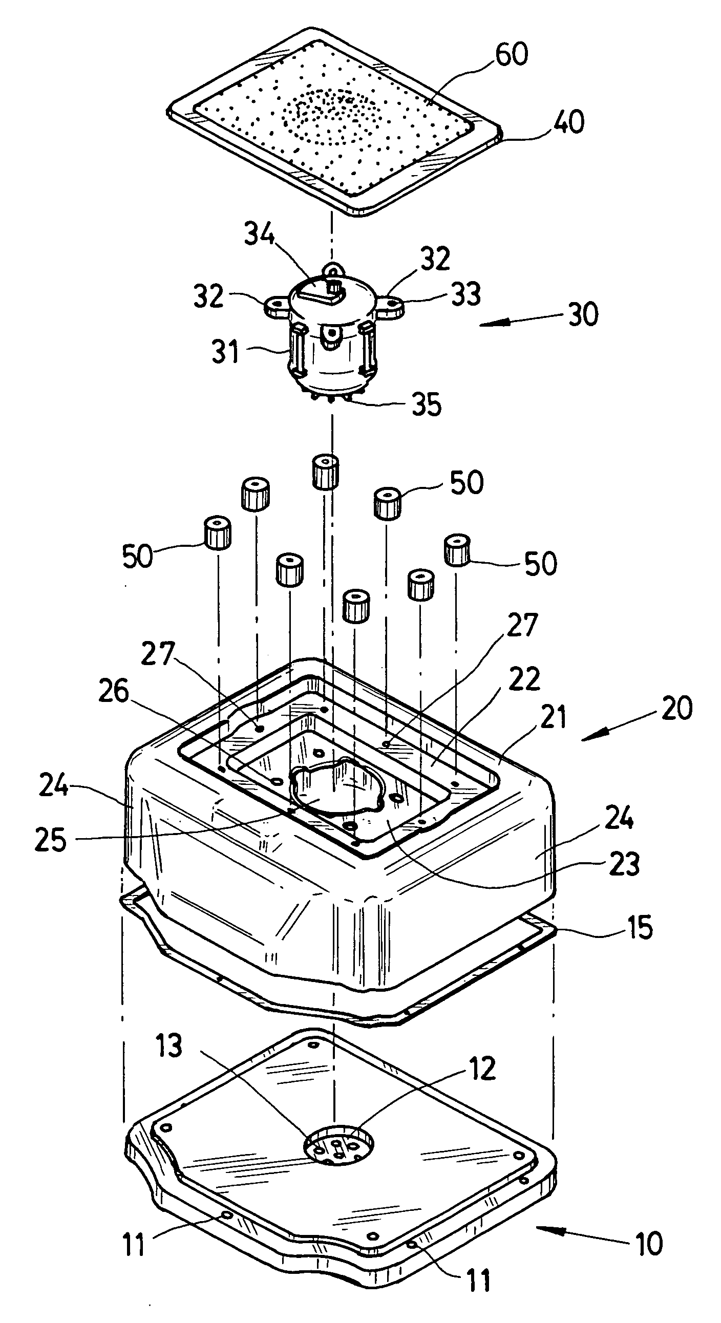
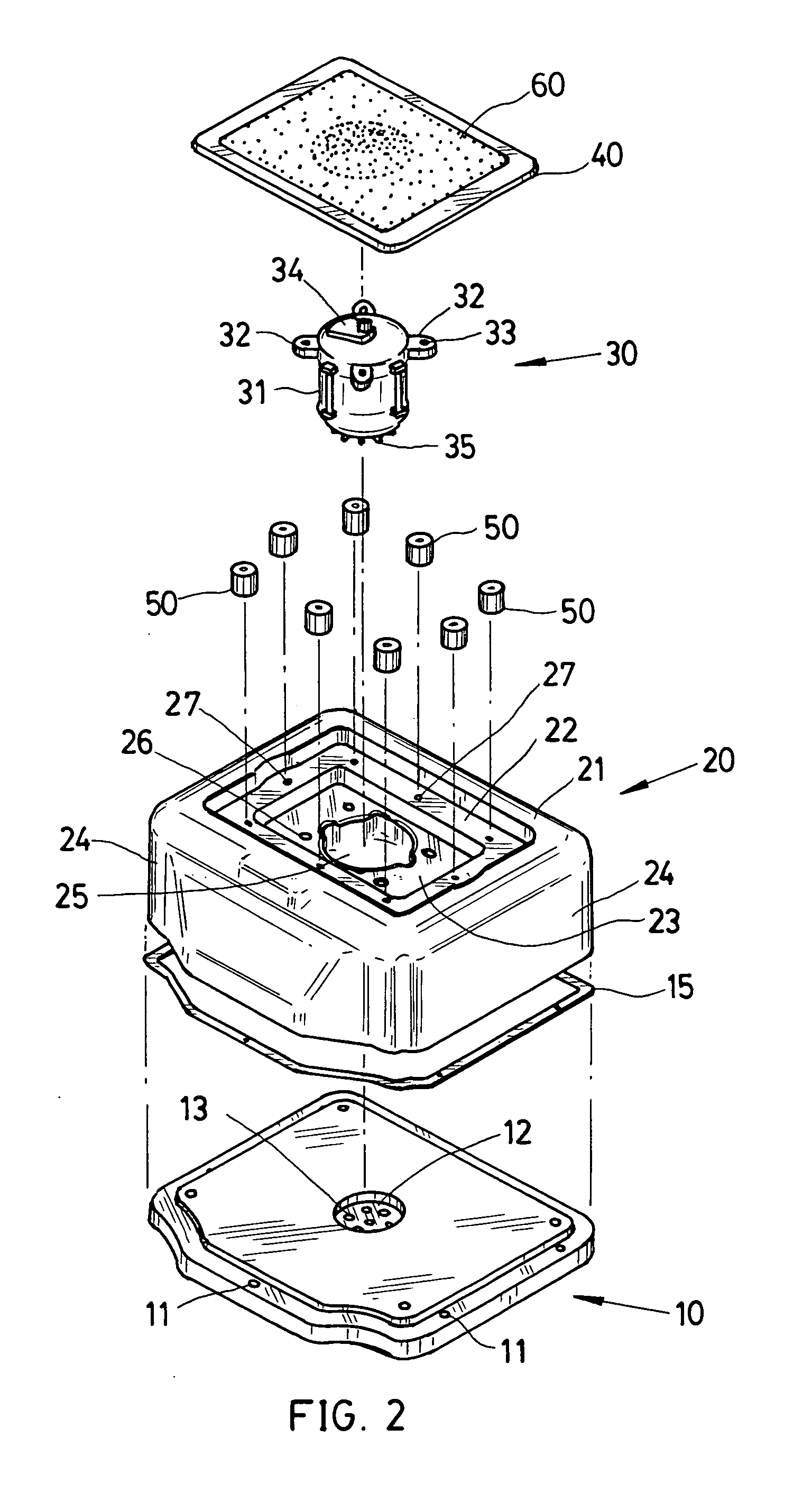
[0018] Referring to FIGS. 2 and 3, a massaging device in accordance with a preferred embodiment of the invention comprises a rectangular base 10, a rectangular-shaped cover 20, a motor 30, a rectangular vibration member 40, a plurality of rubber cylinders 50, and a rectangular massaging pad 60. Each component is discussed in detailed below.

[0019] The base 10 comprises a plurality of threaded holes 11 around its edge such that the base 10 and the cover 20 may be threadedly secured together. This is well known in the art and a detailed description thereof is therefore deemed unnecessary. Further, the base and the cover 20 may be secured together by means of a different technique. The base 10 further comprises a center recess 12, a plurality of apertures 13 in communication with the recess 12 and its bottom, a plurality of (e.g., four) legs 14 for supporting the base 10 above a supporting ground by a predetermined distance, a peripheral skirt pad 15 or the like mounted between the bas...


PUM


Abstract

A massaging device includes a housing including a recessed top and a channel in the recessed top; a motor having an eccentric shaft securely mounted in the channel; a vibration member mounted on the motor; a massaging pad mounted on the vibration member; and a plurality of rubber cylinders mounted around an edge of the recessed top and secured to a bottom of the vibration member. The housing further includes means for absorbing the force of shocks and jarring generated by the activating motor. A peripheral gap is formed between the motor and an inner surface of the channel. The motor further includes a bottom fan adapted to introduce cool air from an underside of the housing into the housing for dissipating heat generated by the activating motor through the gap.

Description

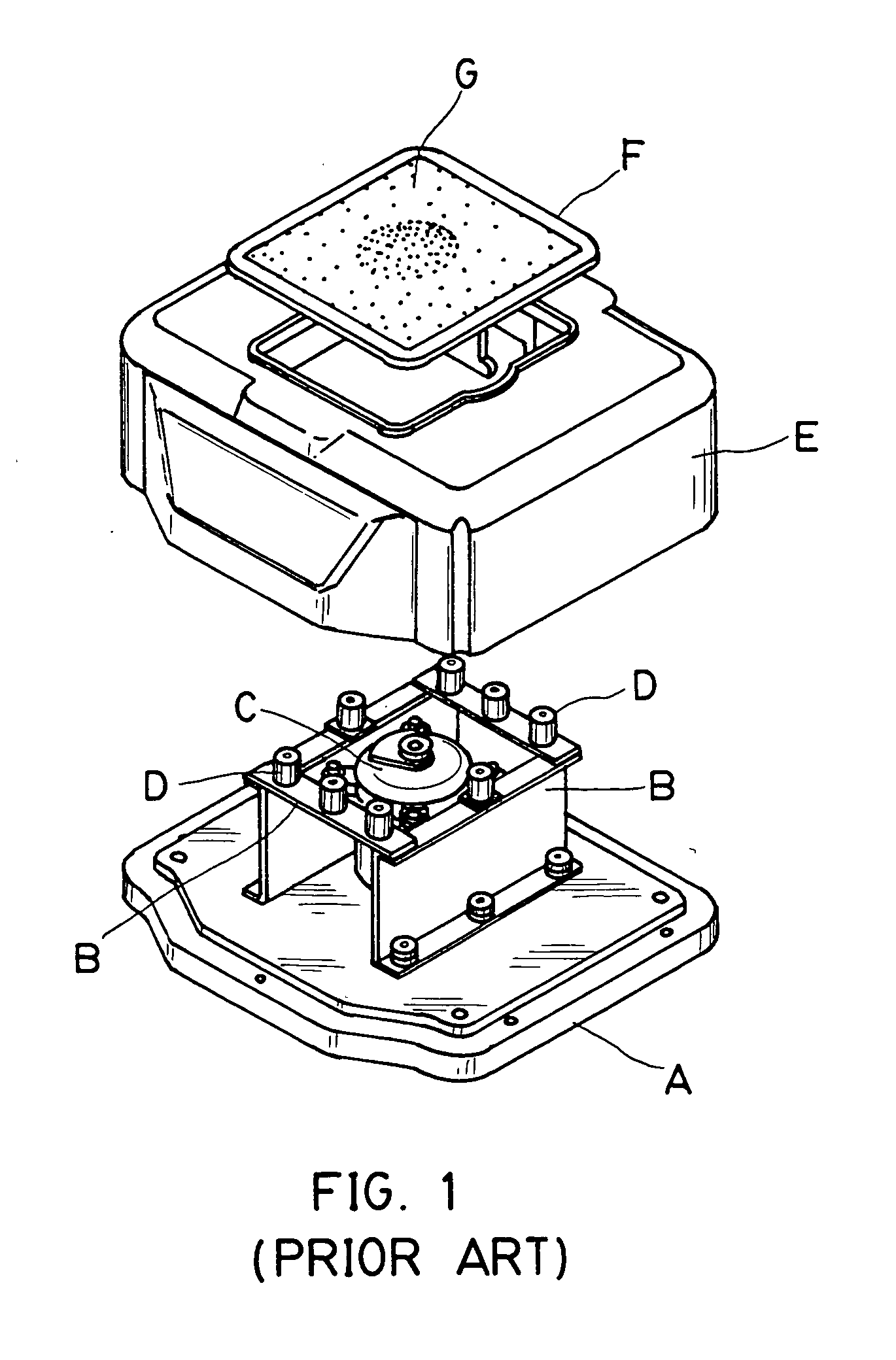
BACKGROUND OF THE INVENTION [0001] 1. Field of Invention [0002] The present invention relates to massaging devices and more particularly to a vibration-type massaging device with improved characteristics including increased stability during operation. [0003] 2. Related Art [0004] Many beneficial effects upon the human body of various forces and motions (e.g., vibration and massage) have long been recognized. Thus, a variety of massaging devices and machines for applying physical forces to the body are commercially available. [0005] A conventional massaging device is shown in FIG. 1 and comprises a base A, a bracket B mounted on the base A, a motor C having an eccentric shaft mounted in the bracket B, a plurality of rubber cylinders D formed around a top edge of the bracket B, a rectangular-shaped cover E put on the base A to seal the above components, a rectangular vibration member F mounted on both the motor C and a top of the cover E, and a rectangular massaging pad G formed on th...

Claims


Application Information

Patent Timeline
Patent Type & Authority Applications(United States)
IPC IPC(8): A61H1/00
CPCA61H1/005A61H2201/0142A61H2201/0138A61H23/0263
Inventor WEN, TSAI YULI-CHU, YUYI-CHIA, CHEN
Owner WEN TSAI YU
Learn More