Method and system for verifying equivalence of two representations of a stimulus pattern for testing a design

a stimulus pattern and equivalence technology, applied in the field of verification designs, can solve problems such as the inability to establish the equivalence between the supposedly correct tbdpatt-formatted pattern and the ate-formatted pattern, and the loss of tolerance of microprocessor users for being error-prone,

Inactive Publication Date: 2007-09-20
IBM CORP
View PDF0 Cites 0 Cited by
  • Summary
  • Abstract
  • Description
  • Claims
  • Application Information

AI Technical Summary

Problems solved by technology

Whether the impact of errors would be measured in human lives or in mere dollars and cents, consumers of microprocessors have lost tolerance for error-prone results.
Consumers will not tolerate, by way of example, miscalculations on the floor of the stock exchange, in the medical devices that support human life, or in the computers that control their automobiles.
The TBDpatt patterns generated by the DFT team do not run on the tester in their native form, because the tester does not accept the testbench-generated TBDpatt format.
Because the tester team has to manipulate the TBDpatt-formatted patterns to generate ATE-formatted patterns before the team can run them on the tester, and because there is no software simulation supported for ATE-formatted patterns, the equivalence between the, supposedly correct, TBDpatt-formatted patterns and ATE-formatted patterns cannot be established under the prior art.
Therefore, when an ATE pattern is failing on the tester, but the TBDpatt pattern is passing simulation or failing with a diff

Method used


Image

  • Method and system for verifying equivalence of two representations of a stimulus pattern for testing a design
  • Method and system for verifying equivalence of two representations of a stimulus pattern for testing a design
  • Method and system for verifying equivalence of two representations of a stimulus pattern for testing a design

Examples


Embodiment Construction

[0015] The present invention provides a method, system and computer program product for verifying the equivalence of two representations of a stimulus pattern for testing a design. The present invention is a tool that has the capability to simulate the response of a hardware design to patterns in both ATE and TBDpatt pattern formats. Using the present invention, equivalence can be established between various pattern types. Therefore, the present invention can uncover inaccurate models and translation errors, allowing DFT team members and tester team members to concentrate on debugging real hardware failures on the tester. While the present invention is described with respect to ATE formatted files, additional pattern formats can be supported in the same manner.

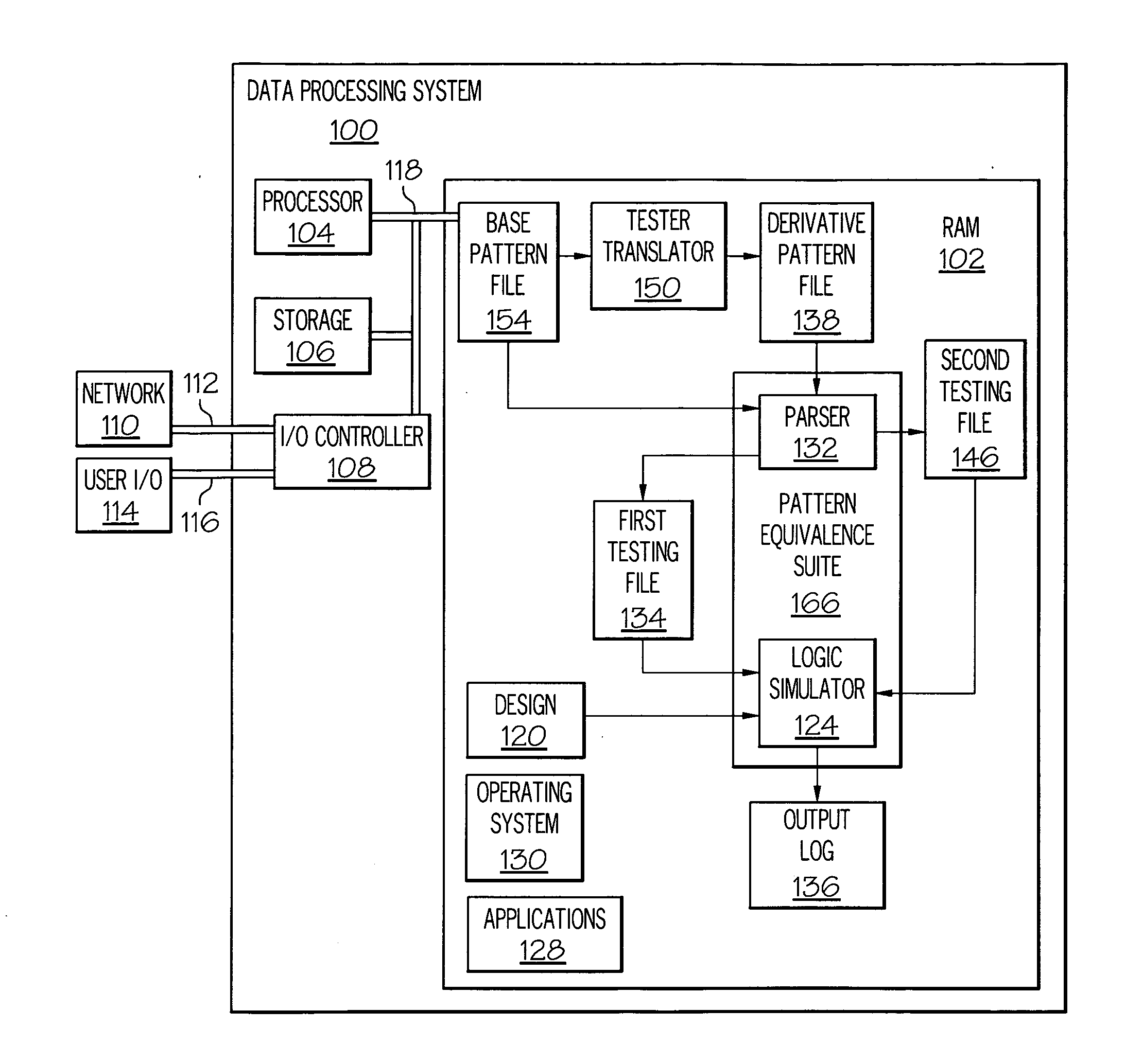
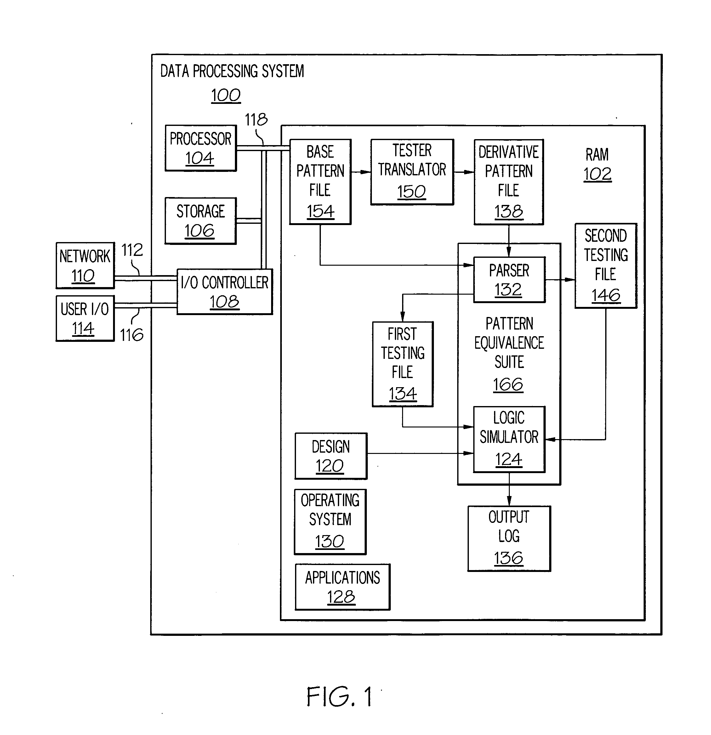
[0016] With reference now to the figures, and in particular with reference to FIG. 1, a block diagram of a general-purpose data processing system, in accordance with a preferred embodiment of the present invention, is depicte...


PUM


Abstract

A method for verifying the equivalence of two representations of a stimulus pattern for testing a design is disclosed. The method includes receiving a base pattern file representing the stimulus pattern in a first file format. A derivative pattern file in a second file format is generated from the base pattern file. The derivative pattern file is parsed to create a first testing file in a third file format, and the first testing file is simulated against the design in a first simulation. Whether the first testing file passed the first simulation against the design is determined, and in response to determining that the first testing file does not pass the first simulation against the design, the base pattern file is parsed to create a second testing file in the third file format. The second testing file is simulated in a second simulation. Whether the second testing file passed the second simulation is determined, and, in response to determining that the second testing file passed the second simulation, a likely non-equivalence of the derivative pattern file and the base pattern file is indicated. In response to determining that the second testing file did not pass the second simulation, a likely equivalence of the derivative pattern file and the base pattern file is indicated.

Description

BACKGROUND OF THE INVENTION [0001] 1. Field of the Invention [0002] The present invention relates in general to verifying designs and in particular to reducing resource requirements during verification. Still more particularly, the present invention relates to a system, method and computer program product for verifying the equivalence of two representations of a stimulus pattern for testing a design. [0003] 2. Description of the Related Art [0004] With the increasing penetration of microprocessor-based systems into every facet of human activity, demands have increased on the microprocessor development and production community to produce systems that are free from data corruption. Microprocessors have become involved in the performance of a vast array of critical functions, and the involvement of microprocessors in the important tasks of daily life has heightened the expectation of reliability of calculative results. Whether the impact of errors would be measured in human lives or in...

Claims


Application Information

Patent Timeline
IPC IPC(8): G01R31/28G06F11/00
CPCG06F17/5022G06F30/33
Inventor BIRD, SARAH L.CHADHA, SUNDEEPDAVIS, MAUREEN T.MORROW, KIRK E.PHAM, TUNG N.
Owner IBM CORP
Why Eureka
Try Eureka