Electromagnetically Driven Valve

a technology of electromagnetically driven valves and valve bodies, which is applied in the direction of valve operating means/release devices, machines/engines, non-mechanical valves, etc., can solve the problems of difficulty in meeting the height requirements of engine mounts, and achieve the improvement of the performance of the oscillating member to move away from the electromagnet, the effect of improving the mounting characteristic and reducing the manufacturing cos

Inactive Publication Date: 2007-09-27
TOYOTA JIDOSHA KK
View PDF14 Cites 0 Cited by
  • Summary
  • Abstract
  • Description
  • Claims
  • Application Information

AI Technical Summary

Benefits of technology

[0015] According to the electromagnetically driven valve structured as above, a parallel link mechanism including a plurality of oscillating members is adopted in the rotary drive type in which the driven valve is caused to reciprocate as a result of an oscillating movement of the oscillating member. By adopting the parallel link mechanism, it is only necessary to arrange an electromagnet implemented by a monocoil between the first oscillating member and the second oscillating member, so as to cause the driven valve to reciprocate by the electromagnetic force generated by the electromagnet and the elastic force applied separately. Therefore, as compared with an example in which the electromagnet constituted of a plurality of coils is arranged in the direction in which the valve shaft extends, the height of the electromagnetically driven valve can be suppressed, and the electromagnetically driven valve can attain improved mounting characteristic. In addition, manufacturing cost of the electromagnetically driven valve can be lowered by the use of the electromagnet implemented by the monocoil.
[0016] Preferably, the electromagnet is configured such that when a direction of a current fed to the monocoil is reversed while any one of the first and second oscillating members is being attracted to the electromagnet, the electromagnetic force acts on any one of the first and second oscillating members that has been attracted to the electromagnet, in a direction away from the electromagnet. According to the electromagnetically driven valve structured as above, performance of the oscillating member to move away from the electromagnet can be improved, and stable oscillating movement and reduction in power consumption can be achieved. In addition, as the electromagnet implemented by the monocoil attains the aforementioned effect, it is not necessary to increase the number of coils.
[0017] Preferably, the first and second oscillating members are provided movably with respect to the driven valve so that a distance between a position where one end is coupled to the valve shaft and a position where the other end is supported by the base member is varied. According to the electromagnetically driven valve structured as above, a distance of oscillation of the first and the second oscillating members on one end side is varied in accordance with change in a distance between one end and the other end. Therefore, a mechanism permitting a distance covered in the reciprocating motion of the driven valve to be variable (hereinafter, also referred to as a lift amount of the driven valve) can be obtained in a simplified and facilitated manner.
[0018] Preferably, the electromagnetically driven valve further includes a sensor portion detecting an angle of oscillation of the first and second oscillating members with the other end serving as a fulcrum. According to the electromagnetically driven valve structured as above, a distance of oscillation of the first and the second oscillating members on one end side is calculated based on an angle of oscillation of the first and second oscillating members detected by the sensor portion and a stroke of the first and second oscillating members, so that a lift amount of the driven valve can be controlled. Therefore, it is not necessary to provide a sensor, for example, at an end portion of the valve shaft in order to control the lift amount of the driven valve, and the height of the electromagnetically driven valve can further be suppressed.
[0019] Preferably, the valve shaft has a buffer member provided between one end of the first oscillating member and one end of the second oscillating member. According to the electromagnetically driven valve structured as above, the buffer member is provided so as to accommodate registration error produced at opposing ends of reciprocating motion of the driven valve. Therefore, the electromagnetically driven valve can achieve desired performance.
[0020] As described above, according to the present invention, an electromagnetically driven valve having a smaller height and attaining excellent mounting characteristic can be provided.

Problems solved by technology

When such an electromagnetically driven valve is used as an intake / exhaust valve in an engine for a vehicle or the like, it is difficult to meet requirements for engine mount height.

Method used


Image

  • Electromagnetically Driven Valve
  • Electromagnetically Driven Valve
  • Electromagnetically Driven Valve

Examples


first embodiment

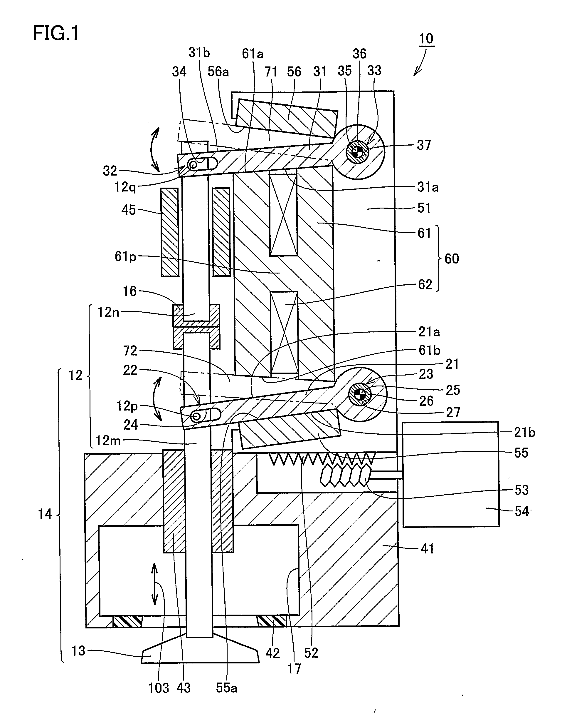
[0035] The electromagnetically driven valve according to the present embodiment implements an engine valve (an intake valve or an exhaust valve) in an internal combustion engine such as a gasoline engine or a diesel engine. In the present embodiment, description will be given assuming that the electromagnetically driven valve implements an intake valve, however, it is noted that the electromagnetically driven valve is similarly structured also when it implements an exhaust valve.

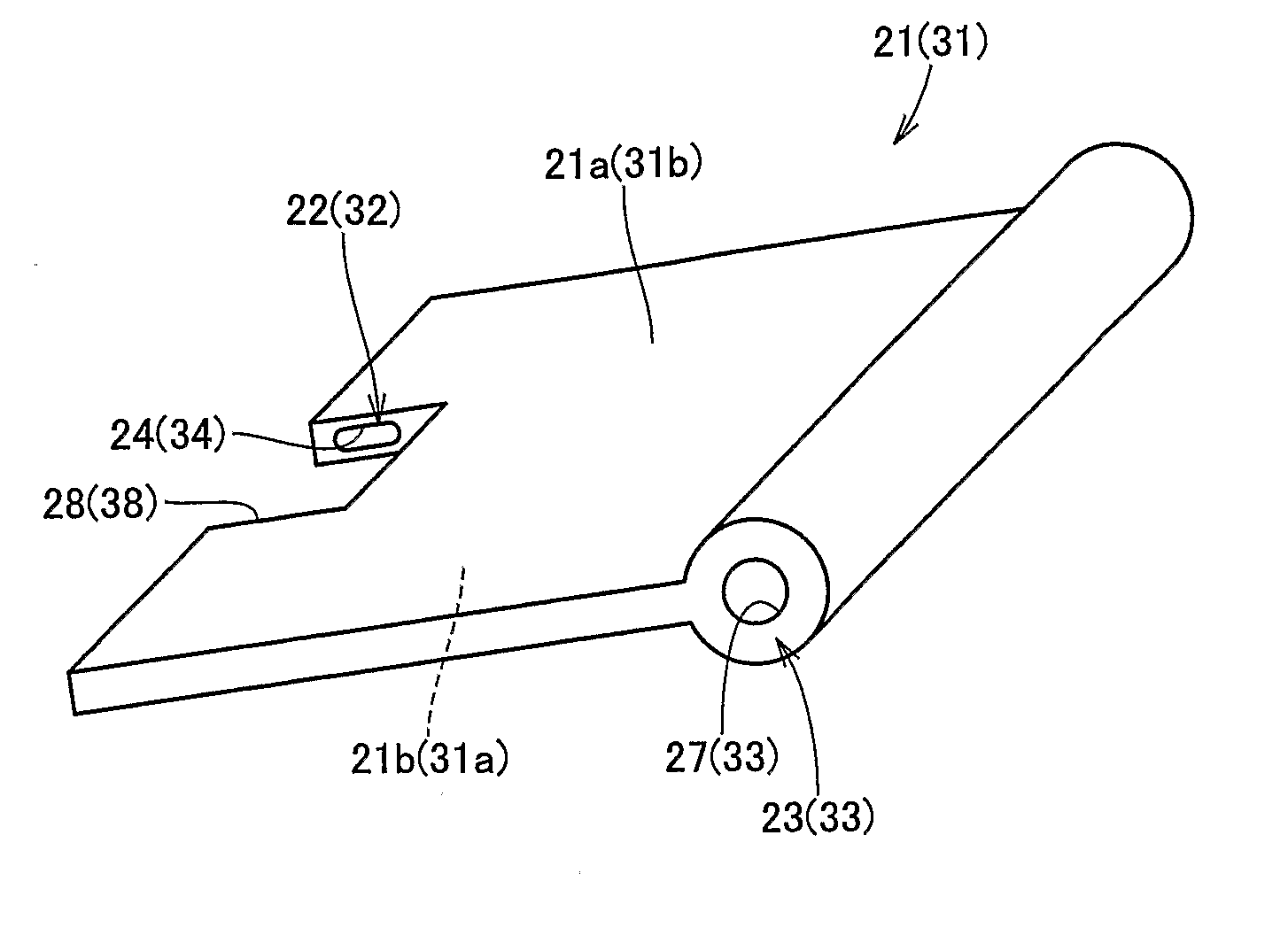
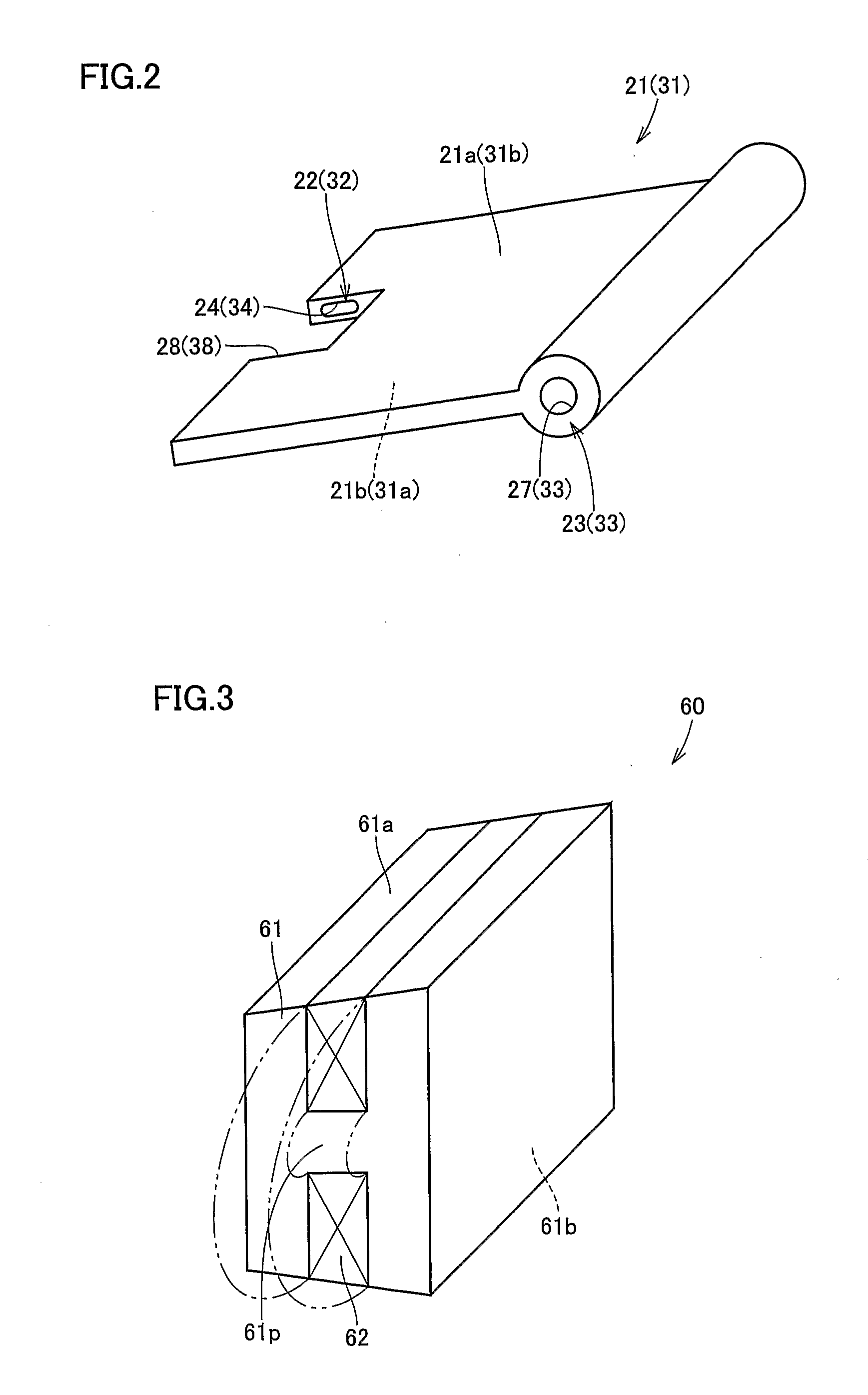
[0036] Referring to FIG. 1, an electromagnetically driven valve 10 is a rotary drive type electromagnetically driven valve. As an operation mechanism for the electromagnetically driven valve, a parallel link mechanism is adopted. Electromagnetically driven valve 10 includes a driven valve 14 having a stem 12 extending in one direction, a lower disc 21 and an upper disc 31 oscillating by receiving electromagnetic force and elastic force applied thereto, a valve-opening / closing electromagnet 60 (hereinafter, ...

second embodiment

[0068] In FIG. 9 showing an electromagnetically driven valve according to a second embodiment of the present invention, the same or corresponding elements as those in electromagnetically driven valve 10 in the first embodiment have the same reference characters allotted. Therefore, description of a redundant structure will not be repeated.

[0069]FIG. 9 shows a spring member 86 provided between umbrella-shaped portion 13 and one end 22 of lower disc 21, spring members 85 and 84 provided at the other end 23 of lower disc 21 and at the other end 33 of upper disc 31 respectively, attraction force generation members 82 and 81 provided between lower disc 21 and upper disc 31, an attraction force generation member 83 provided on a side opposite to attraction force generation member 82 with lower disc 21 being interposed, and an attraction force generation member 80 provided on a side opposite to attraction force generation member 81 with upper disc 31 being interposed.

[0070] Initially, th...

third embodiment

[0075] An electromagnetically driven valve according to the present embodiment is structured in a manner similar to electromagnetically driven valve 10 in the first embodiment, however, a method of supplying the electromagnet with a current is different.

[0076] Referring to FIG. 11, valve-opening / closing coil 62 is supplied with a current flowing in a direction shown with an arrow 121 around shaft portion 61p of valve-opening / closing core 61. Here, magnetic flux flows in valve-opening / closing core 61 in a direction shown with an arrow 122, and upper disc 31 is attracted toward attraction and contact surface 61a of electromagnet 60. Referring to FIG. 12, in the present embodiment, in a state shown in FIG. 11, a direction of the current fed to valve-opening / closing coil 62 is reversed. In other words, a current flowing in a direction shown with an arrow 124 around shaft portion 61p of valve-opening / closing core 61 is momentarily supplied to valve-opening / closing coil 62.

[0077] By rev...


PUM

PropertyMeasurementUnit
electromagnetic forceaaaaaaaaaa
elastic forceaaaaaaaaaa
distanceaaaaaaaaaa

Abstract

An electromagnetically driven valve is actuated by cooperation of electromagnetic force and elastic force. The electromagnetically driven valve includes a driven valve having a stem and carrying out reciprocating motion along a direction in which the stem extends, a lower disc and an upper disc spaced apart from each other and each having one end coupled to the stem so as to allow free oscillation of the disc and the other end supported by a disc base so as to allow free oscillation of the disc, and a lower spring and an upper spring provided at the other end of the lower disc and at the other end of the upper disc respectively and applying elastic force to the lower disc and the upper disc. With such a structure, an electromagnetically driven valve reduced in height and attaining excellent mounting characteristic can be provided.

Description

[0001] This is a 371 national phase application of PCT / JP2005 / 009607 filed 19 May 2005, which claims priority to Japanese Patent Application No. 2004-203370 filed 9 Jul. 2004, the contents of which are incorporated herein by reference. FIELD OF THE INVENTION [0002] The present invention generally relates to an electromagnetically driven valve, and more particularly to an electromagnetically driven valve of a rotary drive type used in an internal combustion engine. BACKGROUND OF THE INVENTION [0003] As a conventional electromagnetically driven valve, for example, U.S. Pat. No. 6,467,441 specification discloses an electromagnetic actuator actuating valves of an internal combustion engine as a result of cooperation of electromagnetic force and a spring. The electromagnetic actuator disclosed in the specification is called a rotary drive type, and includes a valve having a stem and an oscillating arm having a first end hinged on a support frame and a second end in abutment on the upper ...

Claims


Application Information

Patent Timeline
Patent Type & Authority Applications(United States)
IPC IPC(8): F16K31/02F01L9/20H01F7/08H01F7/14
CPCF01L9/04F01L9/20
Inventor SUGIE, YUTAKAASANO, MASAHIKO
Owner TOYOTA JIDOSHA KK
Why Eureka
Try Eureka