
Sheet feeding device and image forming apparatus

a technology of image forming apparatus and feeding device, which is applied in the direction of thin material processing, transportation and packaging, and article separation, etc., can solve the problems of deformation of the image forming apparatus, deformation of the accuracy of the sheet, and deformation of the sheet, etc., and achieve the effect of reliable conveying of the sh

Inactive Publication Date: 2007-09-27
CANON KK
View PDF14 Cites 4 Cited by
  • Summary
  • Abstract
  • Description
  • Claims
  • Application Information

AI Technical Summary

Benefits of technology

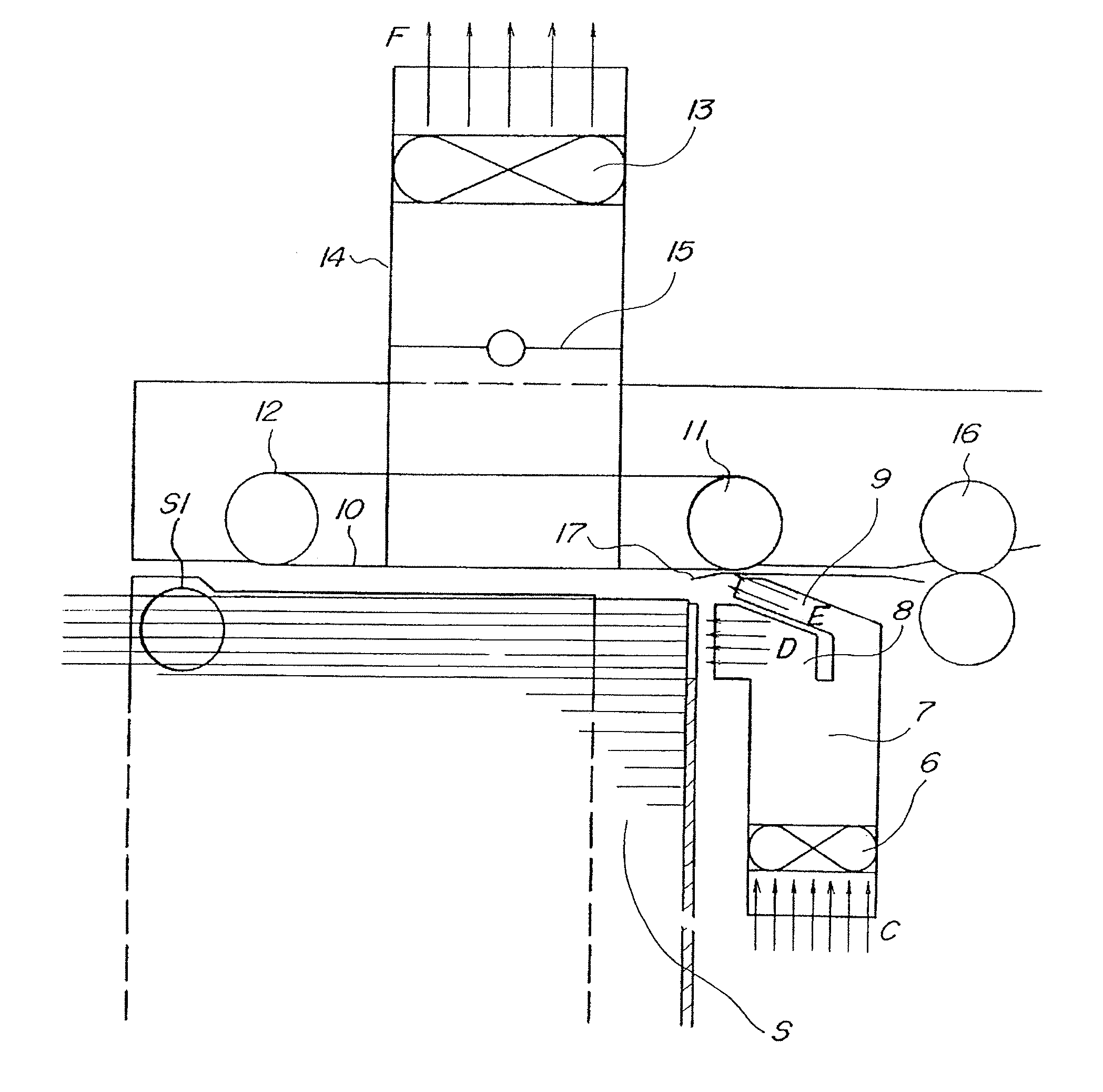
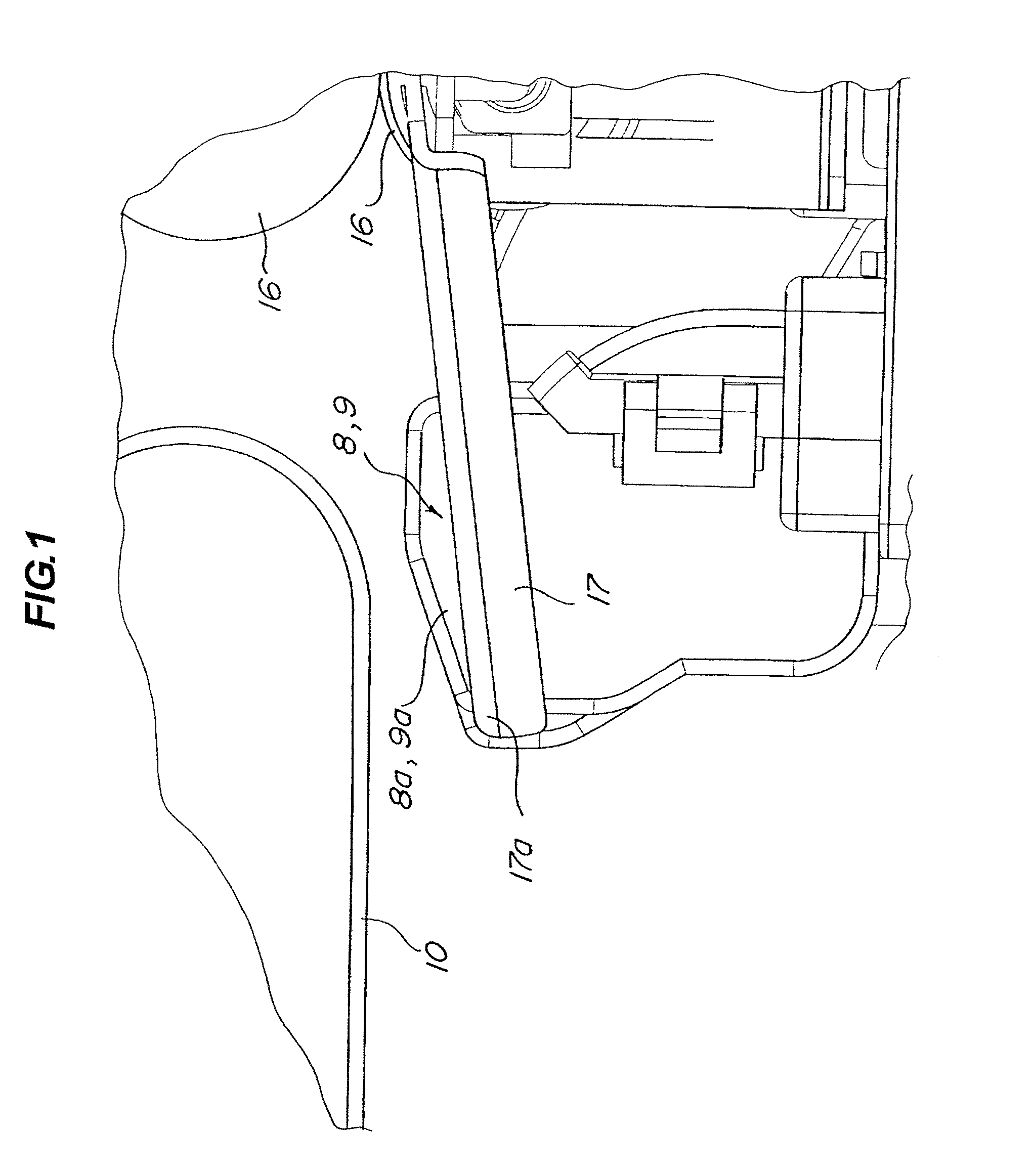
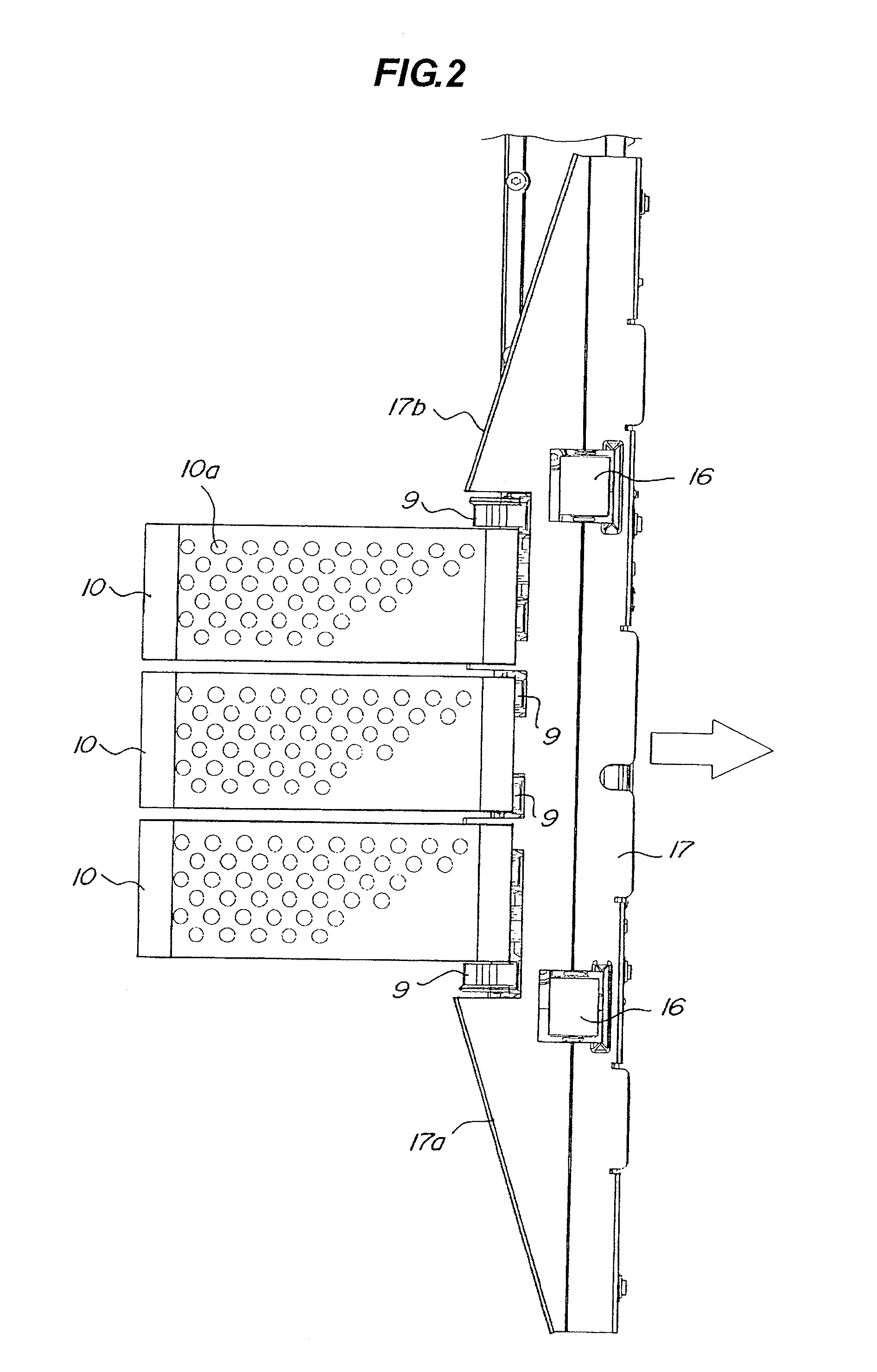
The present invention provides a sheet feeding device that can reliably convey sheets even if there is a level difference between the central portion and the end portion of the sheet when it is adsorbed and conveyed by a conveyance belt. The device includes an air blowing portion that floats sheets by blowing air onto them, an adsorption / conveyance portion that adsorbs and conveys the sheet, a sheet conveyance portion that conveys the sheet to the downstream side, and a conveyance guide that guides the sheet from the adsorption / conveyance portion to the sheet conveyance portion. The conveyance guide has a slope portion that is sloped from the upstream side to the downstream side in the sheet conveyance direction perpendicular to the sheet conveyance direction to both the end portions. This results in a smooth transition of the sheet from the adsorption / conveyance portion to the sheet conveyance portion, ensuring reliable sheet conveyance.

Problems solved by technology

However, in the sheet feeding device which adsorbs a sheet on the conveyance belt 103 to convey the sheet, a portion of the sheet which is not adsorbed by the conveyance belt 103 is hanged down, so that defective conveyance may occur.
However, both the end portions of the sheet in a direction of sheet width are hanged down because the end portions cannot be floated.
At this time, an image forming apparatus may be deteriorated in accuracy to the sheet, or paper jam may be caused.

Method used


Image

  • Sheet feeding device and image forming apparatus
  • Sheet feeding device and image forming apparatus
  • Sheet feeding device and image forming apparatus

Examples


Embodiment Construction

[0031]A sheet feeding device according to an embodiment of the present invention and an image forming apparatus including the sheet feeding device will be described below with reference to the accompanying drawings.

[0032][Entire Configuration of Image Forming Apparatus]

[0033]An entire configuration of the image forming apparatus will be described below together with an image forming operation.

[0034]FIG. 5 is a schematic sectional view for explaining an image forming apparatus having a sheet feeding device. The image forming apparatus according to the embodiment, as shown in FIG. 5, a sheet feeding device A is arranged in a lower part of an image forming apparatus main body (to be referred to as an apparatus main body hereinafter), an image forming portion B which forms an image on a sheet fed from the sheet feeding device A is arranged above the sheet feeding device A. An image reading portion C which conveys an original, optically read information of the original, and converts the ...


PUM


Abstract

The present invention relates to a sheet feeding device includes a sheet tray 2 to place sheets thereon, a nozzle 9 which blows air onto the sheets supported by the sheet tray 2, a conveyance belt 10 to adsorb and convey a sheet floated by blowing air by the nozzle 9, a pulling roller pair 16 which is arranged on a downstream side of the conveyance belt in a sheet conveyance direction and conveys the sheet conveyed by the conveyance belt 10, and a conveyance guide 17 which guides the sheet conveyed from the conveyance belt 10 to the pulling roller pair 16. The conveyance guide 17 has slope portions 17a, 17b which are sloped from an upstream side in the sheet conveyance direction to the downstream side to extend from a central portion in a sheet width direction perpendicular to the sheet conveyance direction to both the end portions.

Description

BACKGROUND OF THE INVENTION[0001]1. Field of the Invention[0002]The present invention relates to a sheet feeding device including an air paper-feeding mechanism which adsorbs an uppermost sheet of a placed sheet stack on a conveyance belt to separately feed the sheets.[0003]2. Description of the Related Art[0004]Some conventional image forming apparatus such as a printer or a copying machine has a sheet feeding device which blows air on an end portion of a sheet stack stored in a sheet storing portion to loosen the sheets and adsorbs the uppermost sheet of the loosened sheets by a conveyance belt to convey the sheets one by one. An example of the sheet feeding device will be described below with reference to FIG. 10. As shown in FIG. 10, air is blown from a loosening nozzle 101 and a separating nozzle 102 onto an end portion of a sheet stack stored in a sheet storing portion 100 to float a plurality of sheets which constitute an upper portion of the sheet stack to loosen the sheets....

Claims


Application Information

Patent Timeline
Patent Type & Authority Applications(United States)
IPC IPC(8): B65H5/08
CPCB65H3/48
Inventor IKEDA, TARO
Owner CANON KK
Learn More