Supercharge Your Innovation With Domain-Expert AI Agents!

Brake control system

a technology of brake control system and relay unit, which is applied in the direction of brake control system, brake safety system, vehicle components, etc., can solve the problem of insufficient consideration of failure between the relay unit and the driving circui

Inactive Publication Date: 2007-09-27
HITACHI LTD
View PDF0 Cites 24 Cited by
  • Summary
  • Abstract
  • Description
  • Claims
  • Application Information

AI Technical Summary

Benefits of technology

The present invention provides a reliable brake control system that can securely feed brake fluid or electric power required to operate predetermined brake calipers even when failure occurs in any one of power supply, actuator driving devices supplied with electric power from the power supply and power lines and power supply lines connected between the power supply and the actuator driving devices. This is achieved by using a brake control system with multiple brake systems supplied with electric power from a plurality of power supplies that are operated independent of each other, and first and second power supply cutting-off means to ensure that the brake systems are securely fed with power.

Problems solved by technology

The above-mentioned conventional brake control system copes with consumption of the batteries but failure between the relay unit and the driving circuit is not considered sufficiently and there is room for improvement in this regard.

Method used


Image

  • Brake control system
  • Brake control system
  • Brake control system

Examples


embodiment 1

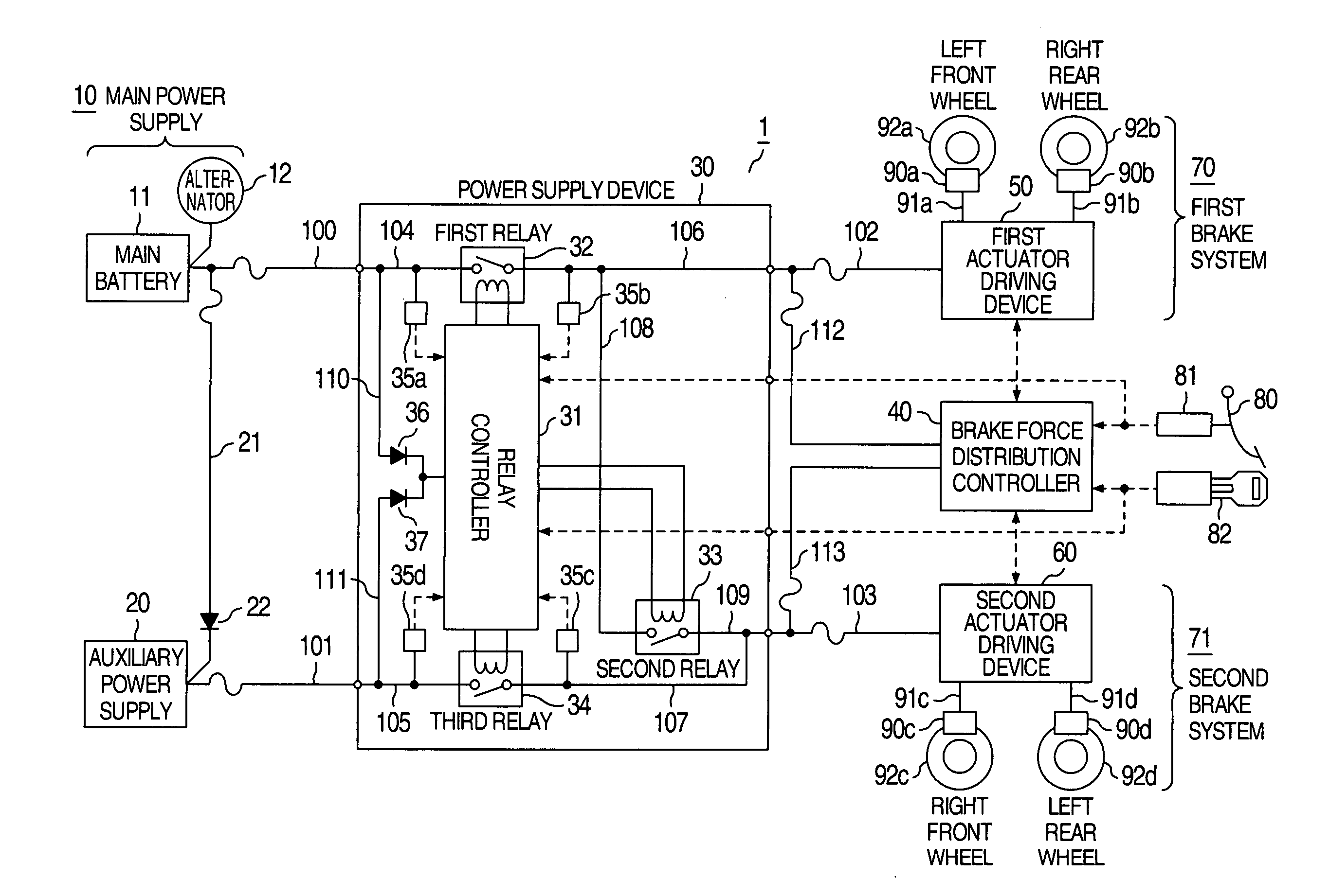
[0039]FIG. 1 is a schematic diagram illustrating the whole configuration of the brake control system 1 according to the first embodiment of the present invention. In FIG. 1, broken lines with arrow represent signal lines and the direction of arrow represents the flow of signal.

[0040]As shown in FIG. 1, the brake control system 1 includes a main power supply 10, an auxiliary power supply 20, a power supply device 30, a brake force distribution controller 40, a brake sensor 81, a first brake system 70 and a second brake system 71.

[0041]The main power supply 10 includes a main battery 11 and an alternator 12.

[0042]The main battery 11 is charged by the alternator 12 coupled with an engine, for example, and supplies the charged electric power to the power supply device 30 through main power line 100.

[0043]The auxiliary power supply 20 is supplied with electric power from the main power supply 10 through power line 21 branching from the main power line 100 and supplies the charged electri...

embodiment 2

[0123]FIG. 6 is a schematic diagram illustrating the whole configuration of the brake control system 1 according to the second embodiment of the present invention. The same elements as those of the first embodiment are designated by the same reference numerals and description thereof is omitted.

[0124]The second embodiment is different from the first embodiment in that a first battery 13 is provided instead of the main power supply 10, a second batter 14 is provided instead of the auxiliary power supply 20, a first power line 120 is provided instead of the main power line 100, a second power line 121 is provided instead of the auxiliary power line 101 and the alternator 12 is connected through a power line 23 to the first battery 13 and through a power line 24 to the second battery 14.

[0125]A diode 25 allows current to flow from the alternator 12 to the first battery 13 and prevents current from flowing from the first batter 13 to the alternator 12. Similarly, a diode 26 allows curre...

embodiment 3

[0152]FIG. 9 is a schematic diagram illustrating the whole configuration of the brake control system 1 according to the third embodiment of the present invention. The same elements as those of the first embodiment are designated by the same reference numerals and description thereof is omitted.

[0153]The third embodiment is different from the first embodiment in that a third actuator driving device 200 is provided instead of the first and second actuator driving devices 50, 60 and the first and second power supply lines 102, 103 are connected to the third actuator driving device 200.

[0154]In the third embodiment, the number of actuator driving devices can be reduced as compared with the first embodiment and the number of failure modes can be reduced correspondingly.

[0155]In the third embodiment, the power supply device 30 and the third actuator driving device 200 can be integrated, so that it is not necessary to provide the first and second power supply lines 102 and 103 and the occu...


PUM


Abstract

At least one of first and second actuator driving devices is supplied with electric power securely. When failure occurs in any one of main power line, auxiliary power line, first and second power supply lines and first and second relays, the first to third relays are controlled to be opened and closed so that failure part is separated or failure part is isolated from part where failure does not occur or supply of electric power to failure part is cut off or electric power is supplied to part to which electric power cannot be supplied.

Description

BACKGROUND OF THE INVENTION[0001]The present invention relates to a brake control system provided with a plurality of power supplies and more particularly to a brake control system that can operate predetermined brake calipers even when failure occurs in a power system.[0002]There is known a prior-art brake control system including disk rotors rotating together with wheels of a vehicle, electro-mechanical calipers disposed near the disk rotors to give electric brake force to the disk rotors, relay units connected to the brake motors in the electro-mechanical calipers through driving circuits and main and auxiliary batteries connected to the relay units (refer to JP-A-11-171006, for example).[0003]JP-A-11-171006 discloses that the driving circuits are energized by the main battery when it is not recognized that the main battery is consumed and the driving circuits are energized by the auxiliary battery instead of the main battery when it is recognized that the main battery is consume...

Claims


Application Information

Patent Timeline
Patent Type & Authority Applications(United States)
IPC IPC(8): B60T8/88
CPCB60T8/885B60T2270/414B60T17/18B60T13/586
Inventor MATSUBARA, KENICHIROKOBAYASHI, HITOSHIINNAMI, TOSHIYUKINISHINO, KIMIOSUGAWARA, TOSHIHARU
Owner HITACHI LTD
Features
  • R&D
  • Intellectual Property
  • Life Sciences
  • Materials
  • Tech Scout
  • Unparalleled Data Quality
  • Higher Quality Content
  • 60% Fewer Hallucinations
Learn More