High efficiency magnet motor

Inactive Publication Date: 2007-09-27
MINKER GARY A
View PDF3 Cites 14 Cited by
  • Summary
  • Abstract
  • Description
  • Claims
  • Application Information

AI Technical Summary

Benefits of technology

[0013] Accordingly, it is a general object of the present invention to provide an improved high efficiency non-el

Problems solved by technology

The consumption of the gasoline required to operate internal combustion engines in these various automotive vehicles and/or machinery causes pollution to th

Method used


Image

  • High efficiency magnet motor
  • High efficiency magnet motor
  • High efficiency magnet motor

Examples


Embodiment Construction

[0031] It is to be distinctly understood at the outset that the present invention shown in the drawings and described in detail in conjunction with the preferred embodiments is not intended to serve as a limitation upon the scope or teachings thereof, but is to be considered merely as an exemplification of the principles of the present invention.

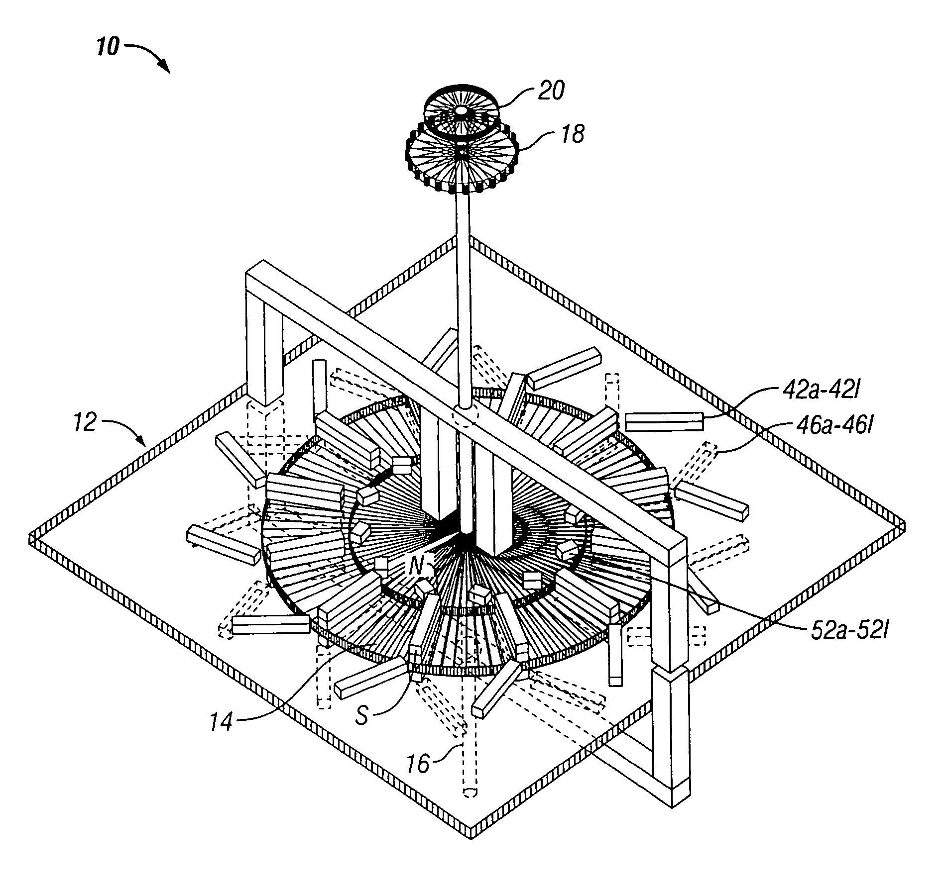
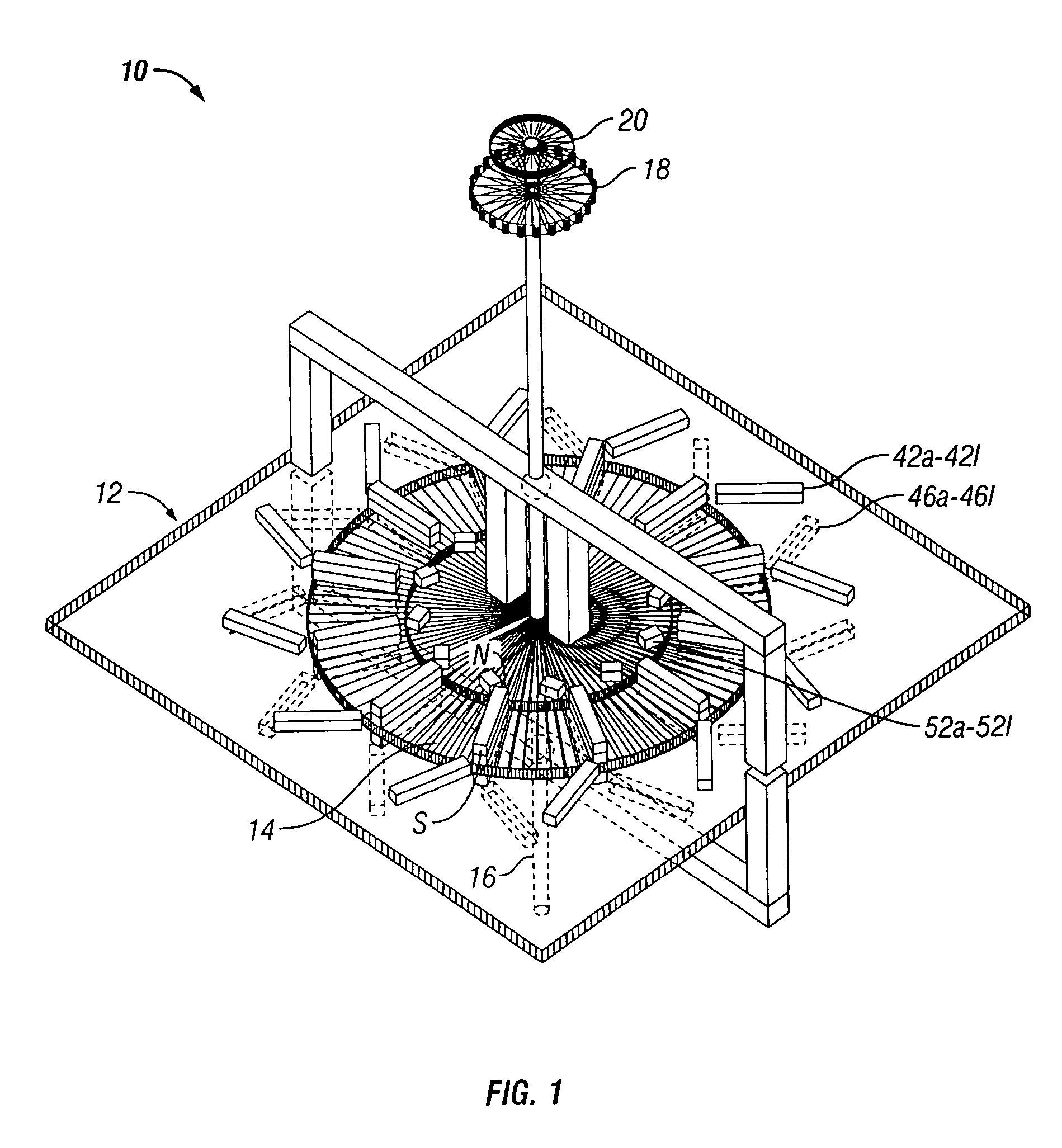
[0032] Referring now in detail to the various views of the drawings, there is illustrated in FIG. 1 a perspective view of a high efficiency magnetic motor 10 in its fully assembled condition, constructed in accordance with the principles of the present invention. The magnetic motor 10 is comprised of a stationary or stator assembly 12 and a relatively rotatable assembly 14 which is also referred to as a rotor or armature assembly. The stator assembly may be formed of any appropriated shape to be operatively supported within a housing or casing (not shown).

[0033] The rotor assembly 14 is mounted rotatably on a rotor shaft 16. A power take-o...


PUM


Abstract

A high efficiency non-electrically induced magnet motor includes a stator assembly and a rotor assembly having a rotor shaft extending therethrough at its center and disposed operatively for relative rotation respect to the stator assembly about the rotor shaft between a counter-clockwise direction and a clockwise direction. First and second groups of magnets are affixed to respective top and lower surfaces of an outer field magnet holder plate of the stator assembly. A third group of magnets is affixed to a top surface of an inner core magnet holder plate of the stator assembly. Fourth and fifth groups of magnets are affixed to respective top and lower surfaces of a rotor plate of the rotor assembly. First and second flux gate window control devices are provided for selectively allowing repulsive flux from the first through third groups of stator magnets to be coupled to the fourth and fifth groups of rotor magnets for causing rotation of rotor assembly between the counter-clockwise and clockwise directions.

Description

BACKGROUND OF THE INVENTION [0001] 1. Field of the Invention [0002] This invention relates generally to magnetically operated motors and more particularly, the present invention relates to an improved high efficiency non-electrically induced magnetic motor, utilizing the effects of stored energy within first through fifth groups of permanent magnets, which is operable independent of gasoline fuel and other similar energy sources so as to avoid contamination of the environment. [0003] 2. Description of the Prior Art [0004] As is generally well-known, there have been produced over the past many years a vast quantity of automotive vehicles, trucks, boats, airplanes and other like machinery which rely heavily upon the use of petroleum fuel such as gasoline for its operation. The consumption of the gasoline required to operate internal combustion engines in these various automotive vehicles and / or machinery causes pollution to the environment. Further, in recent times the cost of gasolin...

Claims


Application Information

Patent Timeline
IPC IPC(8): H02K37/00H02K49/00H02K21/00H02K53/00
CPCH02K53/00
Inventor MINKER, GARY A.
Owner MINKER GARY A
Why Eureka
Try Eureka