Simplified solid state electric motor drive technique

Inactive Publication Date: 2007-09-27
HUGHES WILLIAM
View PDF7 Cites 8 Cited by
  • Summary
  • Abstract
  • Description
  • Claims
  • Application Information

AI Technical Summary

Benefits of technology

[0021] The stators in the variable reluctance electric power system described above may be wound conventionally. That is, for a three phase system, with three tabs of the stator wound with copper wire in one direction and then with the next three tabs wound in series in the other direction. If the tabs were labeled 1, 2, 3, etc., tabs 1, 2, and 3 would be in one winding in, for instance, a clockwise direction and tabs 4, 5, and 6 would be wound in a counterclockwise direction. It should be understood that a second phase would be wound on tabs 2, 3, and 4 and tabs 5, 6, and 7. The third phase would be wound on tabs 3, 4, and 5 and tabs 6, 7, and 8 continuing around the circumference of the stator. As described above, each phase would be a DPDT switch which would include an isolated d-c power source and four switches which might be PBT's, Darlingtons, field effect transistors (FET's), insulated gate bipolar transistors (IGBT's), or, perhaps, silicon control rectifiers (SCR's).
[0022] Many of the problems associated with conventionally wound and driven stators as described above are solved by the use of the stator winding technique of the instant invention. Rather than being wound with a single winding for each phase in a three phase system, the stator winding technique of the instant invention uses two windings per phase. One winding would wrap tabs 1, 2, and 3 and then tabs 7, 8, and 9, etc. A second winding would wrap tabs 4, 5, and 6, and then tabs 10, 11, and 12, etc. The second phase windings would also

Problems solved by technology

In spite of its popularity, the induction motor has several serious drawbacks including: its starting torque is very low, it requires six to eight times its rated full load current to start, and speed control is difficult and requires considerable auxiliary equipment to be accomplished effectively.
This rotor configuration makes them expensive to manufacture, expensive to maintain, and limits the speed at which the rotor can turn and keep the windings safely embedded.
Some d-c rotors have embedded magnets which reduces or eliminates some of these problems, but there is some degra

Method used


Image

  • Simplified solid state electric motor drive technique
  • Simplified solid state electric motor drive technique
  • Simplified solid state electric motor drive technique

Examples


Example

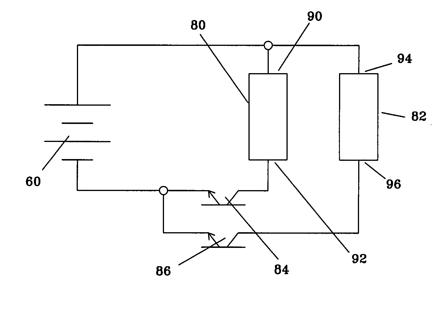
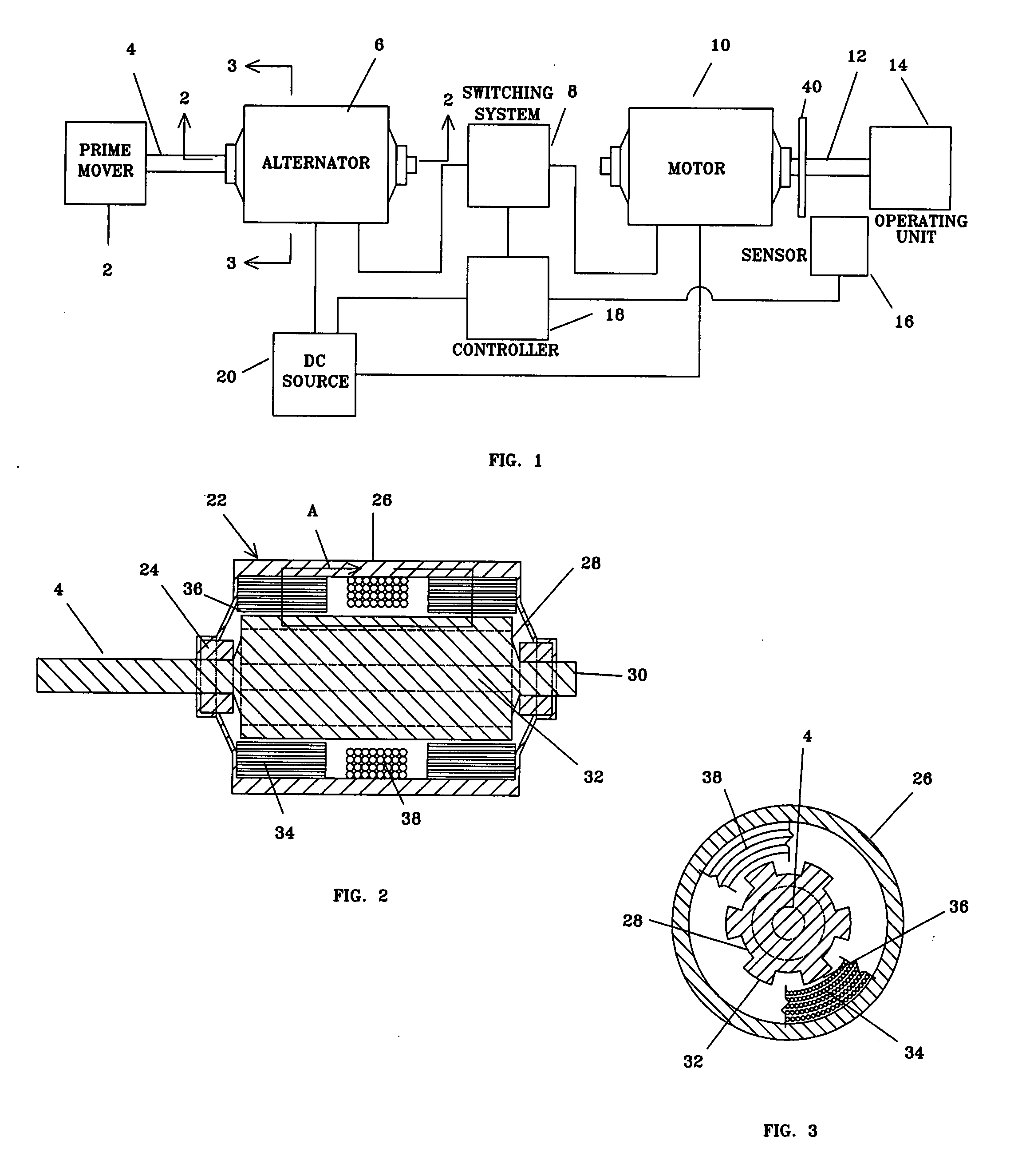
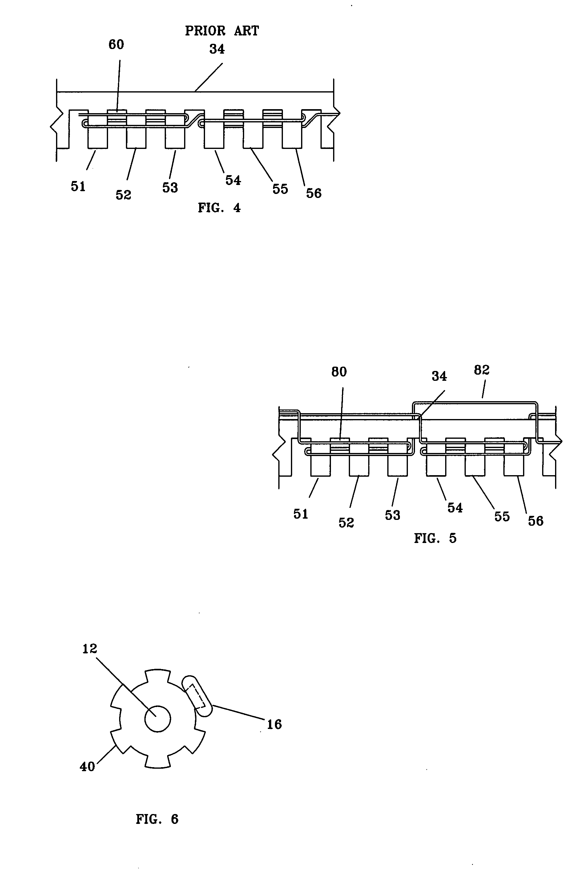
[0036] Referring to the drawings, FIGS. 1, 2, 3, and 6 there is shown a variable reluctance electric power system. FIG. 4 shows a partial view of a conventionally wound stator. FIG. 5 shows a partial view of a stator wound using the stator winding technique which embodies the instant invention. FIG. 7 shows the diagram of a typical DPDT switching system which might be used with one phase of a conventionally wound stator. FIG. 8 shows a diagram of a switching system which might be used with one phase of a stator wound using the stator winding technique of the instant invention.

[0037] Now referring to FIG. 1, a schematic drawing of a variable reluctance electric power system. A prime mover 2 could be any of a number of conventional power sources. For purposes of this discussion, the prime mover 2 will be assumed to be a turbine operating at any speed up to, or perhaps even beyond, 100,000 rpm. Said prime mover 2 is connected by an alternator drive shaft 4 to an alternator 6 of the in...


PUM


Abstract

A simplified solid state electric motor drive technique which may be used with a variable reluctance electric alternator or motor or similar device. The technique comprises the winding of the stator for each phase using two windings rather than the single, in series, winding of a conventional stator winding. A circuit is also provided in which a d-c power supply is connected through a switch to one stator winding and through a second switch to the second stator winding.

Description

BACKGROUND OF THE INVENTION [0001] 1. Field of the Invention [0002] The present invention relates generally to electric power systems and more specifically to a stator winding technique with a simplified solid state electronic motor drive system which may be used with a variable reluctance electric alternator or motor or similar device. [0003] 2. Background Information [0004] In the United States and throughout the world, millions of people use electric motors and alternators on a daily basis. Conventional motors and alternators have a variety of configurations, but ordinarily consist of a metal case (usually steel), a stator which is secured inside the case, and a rotor which turns on bearings mounted at the ends of the case. There are other electric motor configurations, but a great majority have this configuration. A stator usually includes a series of laminations with interior windings, usually of copper wire. The laminations are insulated from each other, are stacked, and are c...

Claims


Application Information

Patent Timeline
IPC IPC(8): H02P1/46
CPCH02K3/28H02P25/085H02K19/103H02P25/092
Inventor HUGHES, WILLIAM
Owner HUGHES WILLIAM
Why Eureka
Try Eureka