Flexible disposable lightweight secure handcuff system

Active Publication Date: 2013-07-23
JERSEY TACTICAL
View PDF19 Cites 7 Cited by
  • Summary
  • Abstract
  • Description
  • Claims
  • Application Information

AI Technical Summary

Benefits of technology

The invention is a small, lightweight, portable, and easy-to-use handcuff that can be used to secure a prisoner's wrists. The handcuff has a strap with a knife-edge and a head with a rectangular frame. The strap passes through the head and the knife-edge engages with the frame. The strap has hillocks and deep valleys, and the knife-edge passes over a hillock and falls into an adjacent valley, securely holding the handcuff in place. The handcuff cannot be easily removed without cutting the strap. The knife is permanently attached to the head using an injection molded polymer bolt, preventing dislodgement. The strap has gussets to prevent twisting and wiggling movement, and the handcuff is securely attached to the wrists with a separation force of up to 250 pounds. The handcuff does not loosen or become overly tight in response to pulling, twisting, or wriggling movements by the wrists.

Problems solved by technology

The handcuff is secured by pulling the distal end of the strap that passes through the aperture of the head results in the deformation of the rectangular frame of the proximal head resulting in the tightening action of the strap against both of the prisoner's wrists.
The handcuff is removed by cutting the polymeric strap with a sharp specially designed knife since the knife-edge locking mechanism cannot be defeated by tweezers, pliers, knives and other commonly available instruments.
The distance between the knife-edge and the top of the hillocks is a critical dimension and is generally interference fit in that some force is required to pull the strap through the aperture in the head.
This results in the deformation of the rectangular frame of the proximal head, creating a tightening action of the strap against both of the prisoner's wrists.
The handcuff is removed by cutting the polymeric strap with a sharp specially designed knife, since the knife-edge locking mechanism cannot be defeated by tweezers, pliers, knives and other commonly available instruments.

Method used


Image

  • Flexible disposable lightweight secure handcuff system
  • Flexible disposable lightweight secure handcuff system
  • Flexible disposable lightweight secure handcuff system

Examples


Embodiment Construction

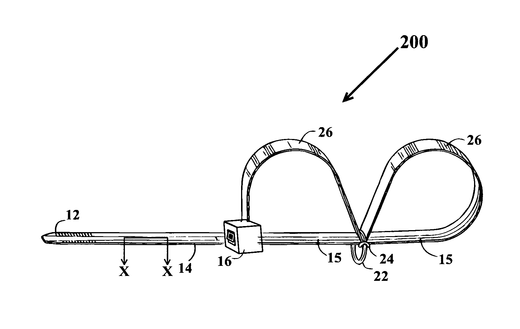
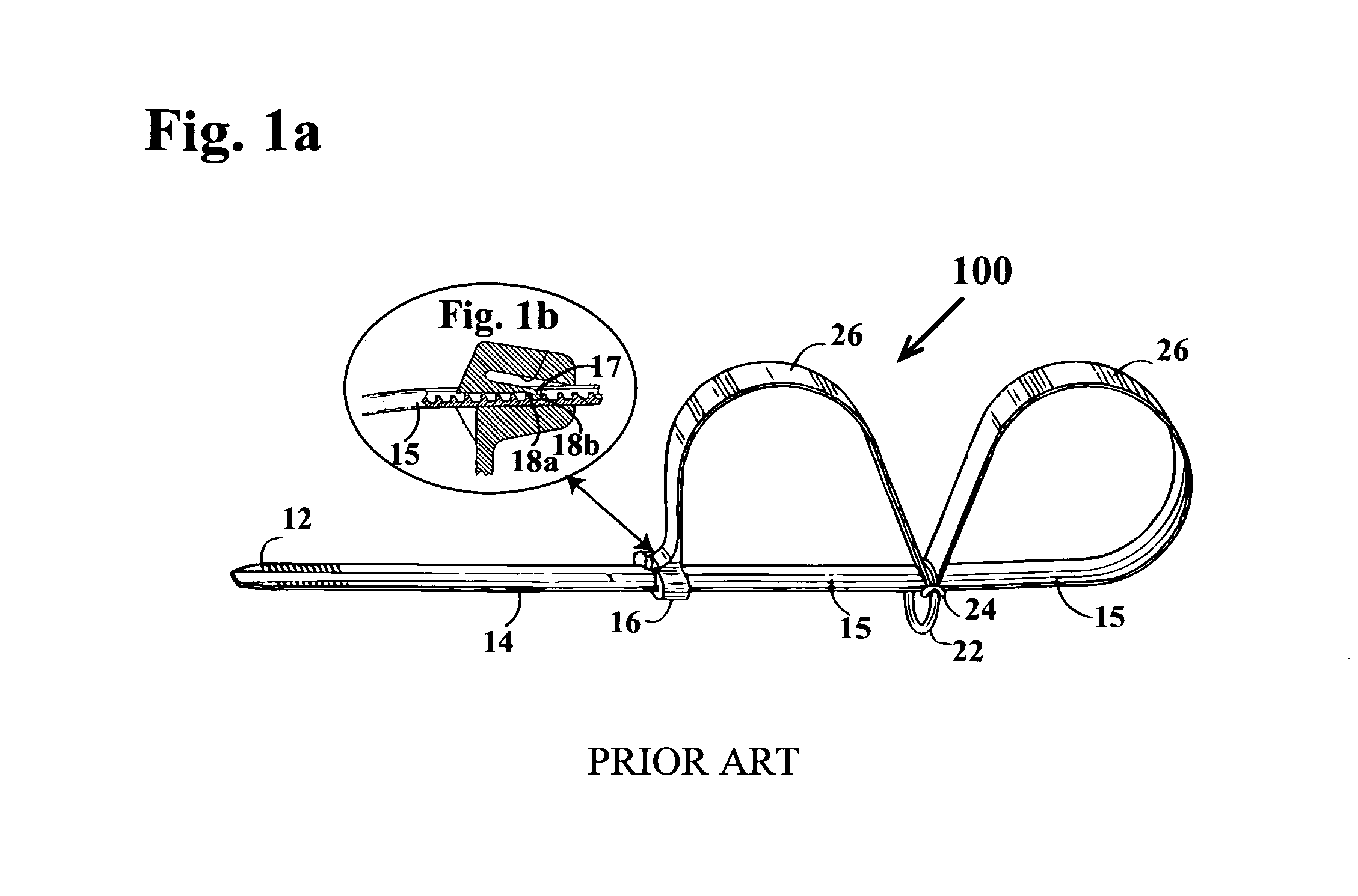
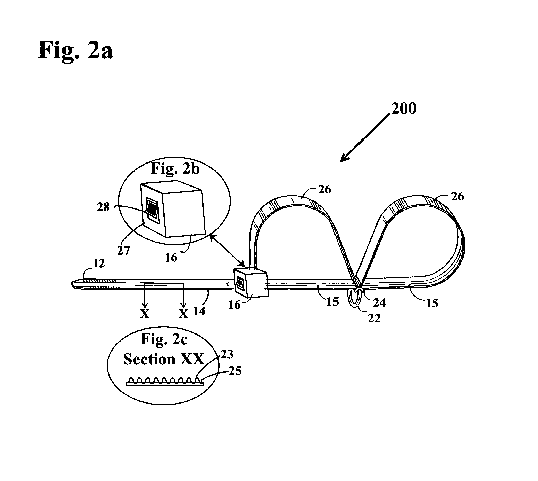
[0044]Handcuffs of various geometries and made from metal and plastic have been known in the art. Metallic handcuffs have been used for a very long time. They are heavy and require keys to secure and unlock their metallic cuff portions. Moreover, an arresting officer can only carry a small number of handcuffs due to their bulk and weight. Plastic handcuffs have been fashioned, imitating the tie wrap geometry wherein a pawl engages with a ratchet. When the strap of the handcuff or tie wrap is pulled through the aperture that carries the pawl, the tip of the pawl engages with the ratchet, which generally has triangularly shaped elements. The pawl element falls within the space between nearly vertical tooth of the ratchet and the gently angled portion of the tooth. When the prisoner pulls against the tie wrap-like handcuff, the vertical wall of the ratchet resists the attempt. Inasmuch as both the pawl and ratchet are made from a polymeric material, they deform easily due to elastic mo...


PUM


Abstract

A compact, lightweight, polymeric injection molded handcuff has a strap with a distal free end and a substantially rectangular head. The strap has knife grabbing features that include a plurality of hillocks with valleys therebetween. The strap head has an aperture surrounded by a deformable frame carrying an integrally molded slanted knife with a sharp knife-edge. The strap's distal end is inserted into the head's aperture and a ring is inserted half way therealong to form two loops for inserting a prisoner's hands therethrough. When the distal end of the strap is pulled to tighten the handcuff, the knife-edge rides the hillocks, which interfere therewith owing to deformation of the head's rectangular portion. Upon clearing the hillocks, the knife comes to rest in one of the valleys, thereby securing the prisoner. Attempts by the prisoner to release the handcuff dig the slanted knife-edge into an adjacent hillock, locking the handcuff.

Description

BACKGROUND OF THE INVENTION[0001]1. Field of the Invention[0002]The present invention relates to handcuffs; and, more particularly, to disposable, flexible, compact, lightweight handcuffs having sufficient pull out strength to prevent escape of a detainee whose hands or legs are secured using a single flexible strap device.[0003]2. Description of the Prior Art[0004]Many patents address issues related to creating handcuffs for securing and retaining prisoners and detainees. Many of these devices are heavy and need keys and locks and the like and require two hand operation.[0005]U.S. Pat. No. 4,071,023 to Gregory discloses a restraining device. The restraining device has an elongated body portion and a pair of arms extending outwardly from the body portion. The first arm has a sharp end that engages with the locking means at the proximal end of the elongated body forming a closed loop for securing one hand of a detainee. The second arm has locking mean provided at the tip distal from ...

Claims


Application Information

Patent Timeline
IPC IPC(8): E05B75/00
CPCE05B75/00Y10T24/1498Y10T70/404
Inventor DAPKINS, JR., JOHN AKLEMENTOWICZ, III, NICHOLAS
Owner JERSEY TACTICAL
Why Eureka
Try Eureka