Multi-terminal harmonic oscillator integrated circuit with frequency calibration and frequency configuration

a multi-terminal harmonic oscillator and integrated circuit technology, applied in oscillation generators, pulse automatic control, resonance circuit tuning, etc., can solve the problems of inability to manufacture as part of the same integrated circuit, affecting the quality of the integrated circuit, and reducing the power dissipation of additional power, etc., to achieve significant noise reduction, phase noise power reduction, phase noise power reduction

Inactive Publication Date: 2007-09-27
INTEGRATED DEVICE TECH INC
View PDF6 Cites 50 Cited by
  • Summary
  • Abstract
  • Description
  • Claims
  • Application Information

AI Technical Summary

Benefits of technology

[0014] Significantly, various exemplary embodiments of the invention generate a significantly and comparatively high frequency, such as in the hundreds of MHz and GHz range, which is then divided to a plurality of lower frequencies. Each such division by “N” (a rational number, as a ratio of integers) results in a significant noise reduction, with phase noise reduced by N and phase noise power reduced by N2. As a consequence, exemplary embodiments of the invention result in significantly less relative period jitter than other oscillators that generate their output directly or through frequency multiplications.

Problems solved by technology

The difficulty with such crystal oscillators is that they cannot be fabricated as part of the same integrated circuit (“IC”) that is to be driven by their clock signal.
For example, because such a processor must be connected through outside circuitry (such as on a printed circuit board (PCB)), power dissipation is comparatively increased.
In applications which rely on a finite power supply, such as battery power in mobile communications, such additional power dissipation is detrimental.
In addition, such non-integrated solutions, by requiring an additional IC, increase space and area requirements, whether on the PCB or within the finished product, which is also detrimental in mobile environments.
Moreover, such additional components increase manufacturing and production costs, as an additional IC must be fabricated and assembled with the primary circuitry (such as a microprocessor).
Other clock generators which have been produced as integrated circuits with other circuits are generally not sufficiently accurate, particularly over fabrication process, voltage, and temperature (“PVT”) variations.
For example, ring, relaxation and phase shift oscillators may provide a clock signal suitable for some low-sensitivity applications, but have been incapable of providing the higher accuracy required in more sophisticated electronics, such as in applications requiring significant processing capability or data communications.
In addition, these clock generators or oscillators often exhibit considerable frequency drift, jitter, have a comparatively low Q-value, and are subject to other distortions from noise and other interference.

Method used


Image

  • Multi-terminal harmonic oscillator integrated circuit with frequency calibration and frequency configuration
  • Multi-terminal harmonic oscillator integrated circuit with frequency calibration and frequency configuration
  • Multi-terminal harmonic oscillator integrated circuit with frequency calibration and frequency configuration

Examples


embodiment 150

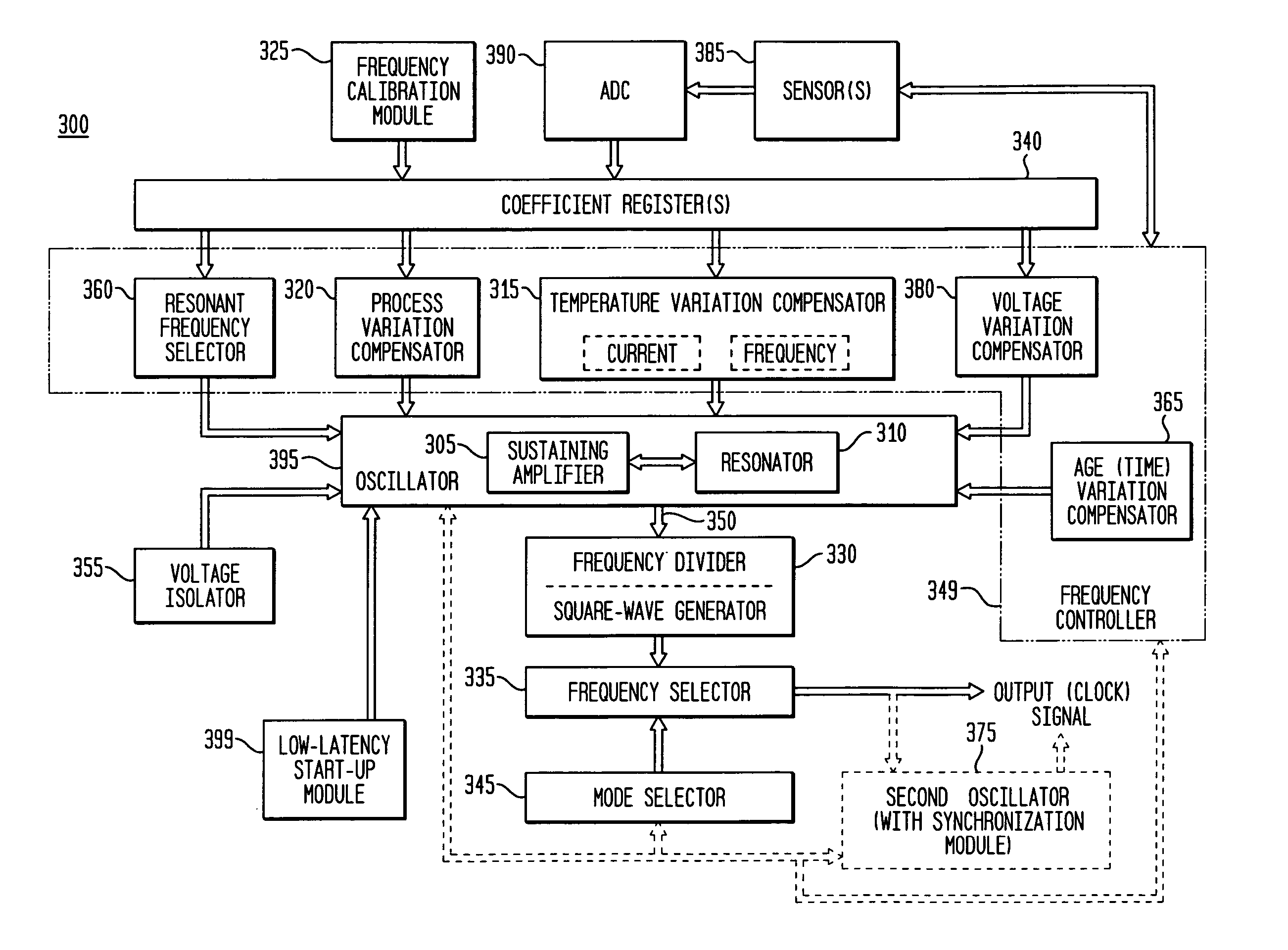
[0085] As indicated above, the various embodiments of the invention provide numerous advantages, including the ability to integrate a highly accurate (over PVT and age), low-jitter, free-running and self-referencing clock generator and / or a timing and frequency reference with other circuitry, such as illustrated in FIG. 1. FIG. 1 is a block diagram illustrating an exemplary system embodiment 150 in accordance with the teachings of the present invention. As illustrated in FIG. 1, the system 150 is a single integrated circuit, having a clock generator and / or timing / frequency reference 100 of the present invention integrated monolithically with other, or second, circuitry 180, together with interface (I / F) (or input / output (I / O) circuitry) 120. The interface 120 will generally provide power, such as from a power supply (not illustrated), ground, and other lines or busses to the clock generator 100, such as for calibration and frequency selection. As illustrated, one or more output cloc...

first embodiment

[0243] In another variation of the first embodiment, the apparatus 3700, 3710, 3800, 3850 may be adapted to enter a calibration mode during initial power up when a first predetermined value is held in the predetermined calibration register (coefficient register (340, 455, 465, 495, 3020)). Alternatively, the apparatus 3700, 3710, 3800, 3850 may be adapted to enter a reference (or clock) mode during initial power up when a second predetermined value is held in the predetermined calibration register. In addition, the apparatus 3700, 3710, 3800, 3850 may be adapted to enter a frequency configuration mode during initial power up when a first or second predetermined (configuration) value is held in a configuration register (also typically part of a coefficient register (340, 455, 465, 495, 3020)). Those having skill in the art will recognize that numerous other variations of this calibration or configuration sensing (and corresponding bit / value storage) are also available and equivalent,...


PUM


Abstract

Exemplary embodiments of the invention provide a reference harmonic oscillator integrated circuit having three or more terminals, with systems and methods for calibrating the harmonic oscillator to a selected first frequency using a limited number of terminals. An exemplary apparatus comprises: a reference harmonic oscillator, a first terminal to receive a supply voltage, a second terminal to receive a ground potential, a third terminal to provide an output signal having an output frequency, and may also include a fourth terminal. One of the first, second, third or fourth terminals is further adapted for input of a calibration of the first frequency. The exemplary apparatus may enter calibration and testing modes in response to various commands such as a calibration mode signal, and may also be configured through one of the terminals for output frequency selection, spread-spectrum output, and output voltage levels.

Description

CROSS-REFERENCE TO RELATED APPLICATIONS [0001] This application is a continuation-in-part of and claims priority to U.S. patent application Ser. No. 11 / 232,409, filed Sep. 20, 2005, inventors Michael Shannon McCorquodale, Scott Michael Pemia, Sundus Kubba, and Amar Sarbbaseh Basu, entitled “Frequency Calibration for a Monolithic Clock Generator and Timing / Frequency Reference” (the “first related application”), which is commonly assigned herewith, the contents of which are incorporated herein by reference, and with priority claimed for all commonly disclosed subject matter, which is a continuation-in-part of and further claims priority to U.S. patent application Ser. No. 11 / 084,962, filed Mar. 21, 2005, inventors Michael Shannon McCorquodale, Scott Michael Pemia, and Amar Sarbbaseh Basu, entitled “Monolithic Clock Generator and Timing / Frequency Reference” (the “second related application”), and further claims priority to U.S. Provisional Patent Application Ser. No. 60 / 555,193, filed ...

Claims


Application Information

Patent Timeline
Patent Type & Authority Applications(United States)
IPC IPC(8): G01R23/00
CPCH03B2201/025H03J2200/10H03L1/022H03L1/023H03B5/124H03B5/1228H03B5/1212H03B2200/0038H03B5/1221H03L7/089
Inventor PERNIA, SCOTT MICHAELMCCORQUODALE, MICHAEL SHANNONKUBBA, SUNDUSO'DAY, JUSTINCARICHNER, GORDONMARSMAN, ERIC DAVID
Owner INTEGRATED DEVICE TECH INC
Why Eureka
Try Eureka